

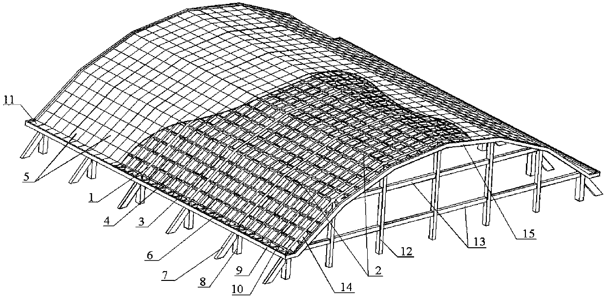
Long-span concrete prismatic surface arch reticulated shell roof structure and manufacturing method thereof
A concrete and prismatic surface technology, applied in roofs, building components, building structures, etc., can solve the problems of low difficulty in formwork and support, and achieve the effect of reducing acoustic treatment costs, simple formwork support, and ensuring construction quality.
- Summary
- Abstract
- Description
- Claims
- Application Information
AI Technical Summary
Problems solved by technology
Method used
Image

Examples
Embodiment 1
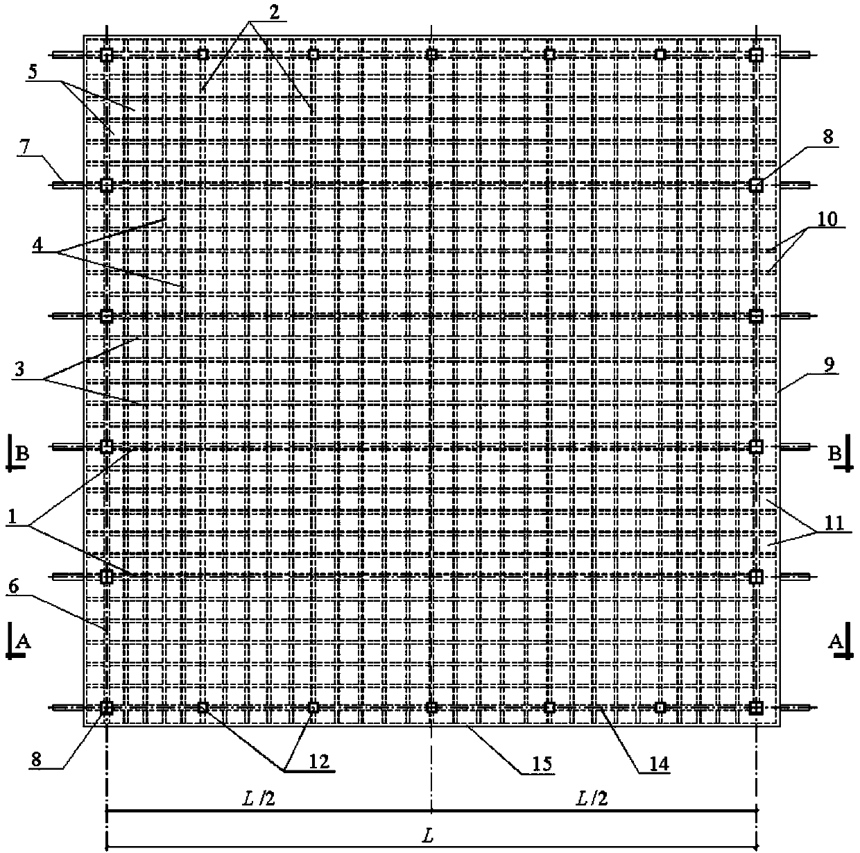
[0035] Embodiment 1 of the present invention: adopt cast-in-place concrete mode to make, refer to figure 1 with figure 2 , the specific implementation steps are:
[0036](1) Bind the steel bars of the anti-push rod 7 and the side frame column 8 and place the formwork thereof, and pour concrete to the beam bottom elevation of the side frame beam 6 .
[0037] (2) Bind the steel bars of the gable frame column 12 and the gable frame interlayer beam 13 and place the formwork, and pour concrete to the beam bottom elevation of the gable frame top beam 14 .
[0038] (3) help tie the reinforcing bars of side frame beam 6 and gable frame top beam 14, and place its side form;
[0039] (4) Set up the scaffolding of the whole hall, place the bottom form of the main broken line arch 1, the ridge beam 2, the transverse rib beam 3, the longitudinal rib beam 4, the gutter rib beam 10 and the gutter sealing beam 9, and place the steel bars of the above components after binding The bottom fo...
Embodiment 2
[0043] Embodiment 2 of the present invention: adopt prefabricated assembly mode to make roof, concrete implementation steps are:
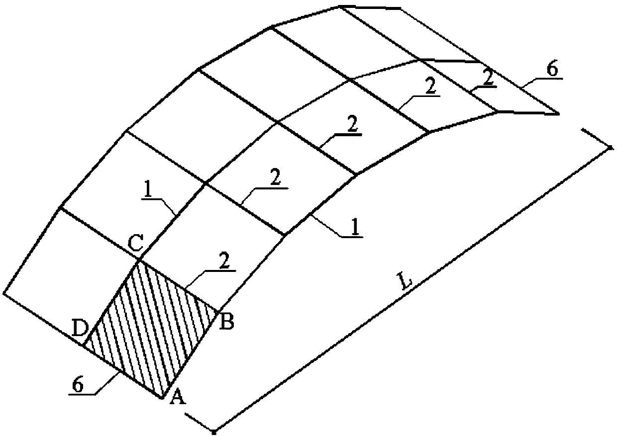
[0044] (1) see Figure 11 with Figure 12 , the prefabricated roof panel 5 and the cross composed of transverse rib beams 3 and longitudinal rib beams 4 are used on the ground. When the cross is made, the concrete within the thickness δ range of the roof panel 5 is not poured. At the central node of the cross, each side of the concrete needs to protrude from the side of the rib by not less than 50mm, which is used for placing the prefabricated roof panel 5 after it is in place.
[0045] (2) see Figure 13 with Figure 14 , Prefabricate the gable frame column 12 and the gable frame beam 13 on the ground, wherein the top of the gable frame column 12 is embedded with an embedded part 15 matched with angle steel and bolts, for the temporary support of the gable frame beam 13 in place when the gable frame is assembled.
[0046] (3) see figure 1 wit...
PUM
 Abstract
Description
Claims
Application Information