
Tire comprising a high-contrast pattern and ribs for protecting the pattern

a technology of high-contrast patterns and ribs, which is applied in the direction of manufacturing tools, transportation and packaging, other domestic objects, etc., can solve the problems of relatively fragile patterns, relatively small differences in contrast between patterns and the rest of the sidewalls, and relatively fragile patterns

Active Publication Date: 2014-08-07
MICHELIN & CO CIE GEN DES ESTAB MICHELIN +1
View PDF1 Cites 12 Cited by
  • Summary
  • Abstract
  • Description
  • Claims
  • Application Information

AI Technical Summary

Benefits of technology

The patent text describes a method to make a tire with a pattern of ribs that are more durable and visually appealing. The method involves enhancing the pattern by making it more robust and ensuring a more durable contrast between the pattern and the rest of the sidewall. This is achieved by angling the strands or strips that make up the pattern, making them less likely to detach from the tire. The method also involves orienting the ribs in a radial direction, which optimizes their ability to bear forces from kerbing, and produces striations on a mold that can be easily used to mold ribs on a sidewall of a tire.

Problems solved by technology

However, a pattern comprising such strands may be relatively fragile when faced with certain forms of mechanical attack, such as kerbing in which it is rubbed against a kerb.
Although the strips are better able to withstand the mechanical loadings encountered during kerbing, the pattern is still relatively fragile and the difference in contrast between the pattern and the rest of the sidewall fades fairly rapidly by comparison with the service life of the tire.

Method used


Image

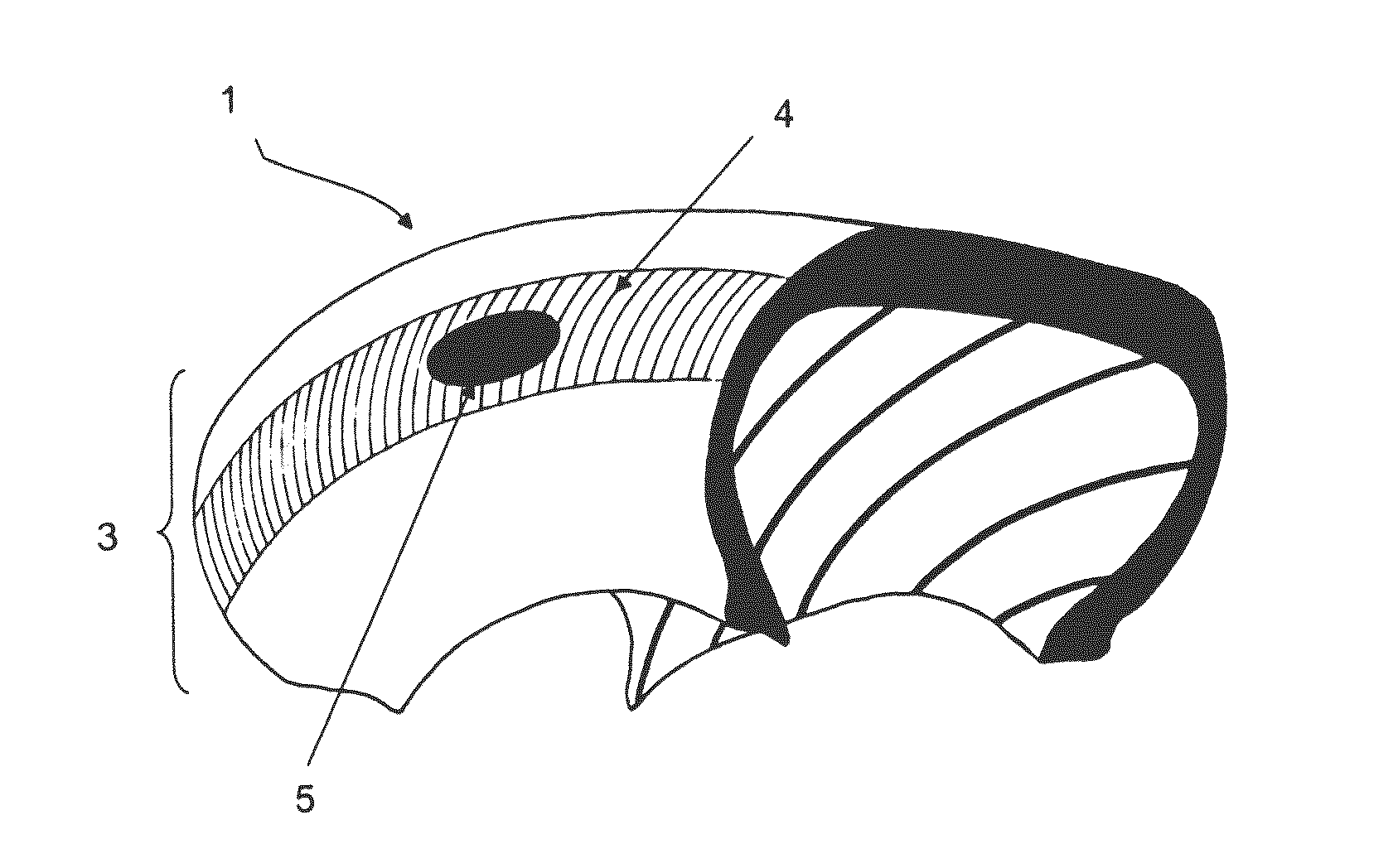
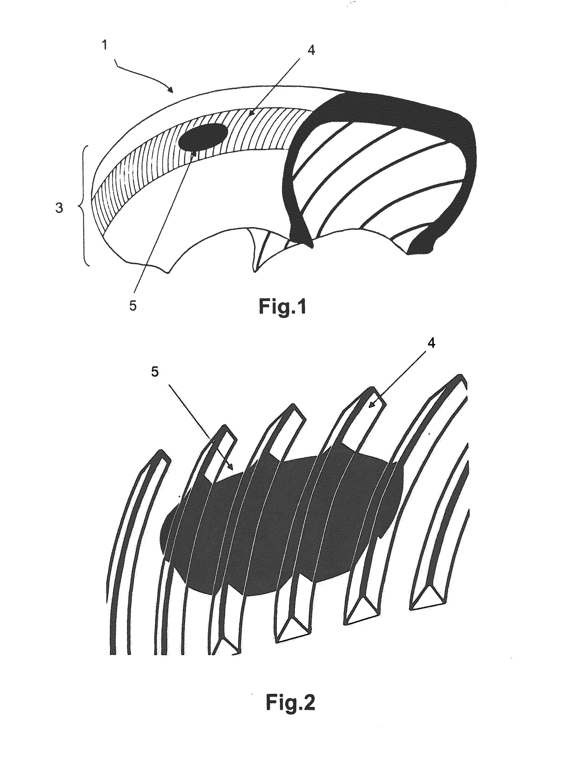
  • Tire comprising a high-contrast pattern and ribs for protecting the pattern
  • Tire comprising a high-contrast pattern and ribs for protecting the pattern
  • Tire comprising a high-contrast pattern and ribs for protecting the pattern

Examples


first embodiment

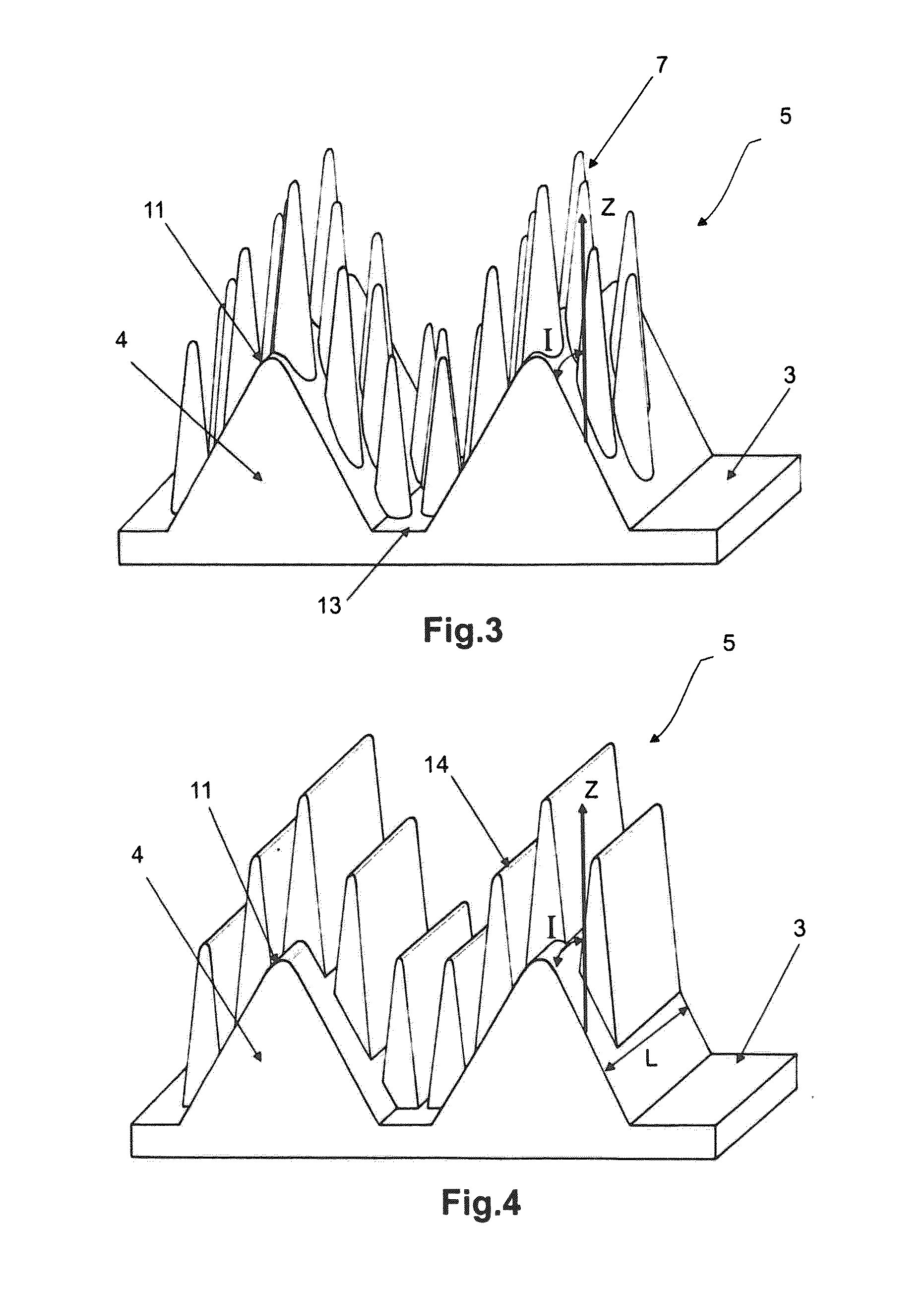
[0054]FIG. 3 is a perspective view of the pattern 5 of FIG. 1.

[0055]In this embodiment, the pattern 5 is formed by a plurality of strands 7. Some of these strands extend between two tops 11 of two adjacent ribs 4. More specifically, strands cover a residual area 13 delimited by bases of the two adjacent ribs. Strands also cover the lateral walls of the ribs. Specifically, each rib has two lateral walls extending one on each side of their top 11. The lateral walls of the ribs 4 are, for example, inclined by an angle a which, in terms of absolute value, is between 30° and 60° to a direction Z perpendicular to the sidewall. Thus, the walls of the ribs when not covered with strands have a low ability to “trap” the incident rays of light. Thus, when the ribs extend all around the circumference of the tire, as they do in the example of FIG. 1, the pattern can be sure to contrast markedly with the sidewall and particularly with those zones of the sidewall which are covered by these ribs.

[0...

second embodiment

[0058]FIG. 4 is a perspective view of the pattern 5 of FIG. 1.

[0059]In this embodiment, the strands of the pattern are replaced by strips 14 the mean width of which is less than the mean width of the ribs 4. The mean width of the strips in the pattern is thus between 0.03 and 0.10 mm and the mean width of the ribs in the pattern is at least equal to 0.20 mm The “mean width” of a rib or of a strand, respectively, means the mean of the widths measured at regular intervals from the root of the rib, or of the strand respectively, to the tip, the width of a rib or, respectively, of a strip, corresponding to the distance measured between two lateral walls of this rib or of this strip respectively.

[0060]In addition, the height of the strips in the pattern is at least equal to 0.1 mm and the height of the ribs in the pattern is between 0.25 mm and 1 mm.

[0061]The strips are depicted here as being parallel to the ribs. As an alternative, the strips may make a non-zero angle with the direction...


PUM

PropertyMeasurementUnit
widthaaaaaaaaaa
heightaaaaaaaaaa
heightaaaaaaaaaa

Abstract

The invention relates to a tire made of rubbery material comprising a sidewall on which there is formed at least one pattern that contrasts with this sidewall. The pattern comprises a plurality of strands distributed through the pattern with a density of at least five strands per square millimetre (mm2), each strand having a mean cross section of between 0.003 mm2 and 0.06 mm2. The tire also comprises on the said sidewall at least two ribs that pass through the pattern and between which strands of the pattern are present, the said ribs being distant from one another by at most 10 mm, each rib having a height of at least 0.25 mm and a mean width of at least 0.20 mm, the said pattern following the relief formed by the ribs.

Description

[0001]This application claims benefit of the filing date of PCT / EP2012 / 060201, filed May 31, 2012, which claims the benefit of FR1155208, filed Jun. 15, 2011, the entire contents of each of which are incorporated herein by reference for all purposes.FIELD[0002]Disclosed herein is a tire for a motor vehicle having a high-contrast pattern and also relates to a mold for molding and vulcanizing the said tire and to a method for manufacturing this mold.DESCRIPTION OF RELATED ART[0003]The tire sidewalls display a great many patterns intended on the one hand to provide technical and legal information and, on the other hand, to allow the consumers to discern the origin of the product.[0004]Attempts are continually being made to improve the visibility and legibility of these patterns on tire sidewalls.[0005]Document WO2007 / 045425 describes a high-contrast pattern comprising a plurality of strands projecting from a surface of the tire. “Strand” here means a filiform element the height of whic...

Claims


Application Information

Patent Timeline
Patent Type & Authority Applications(United States)
IPC IPC(8): B60C13/02B23K26/00B23K26/36B29D30/06
CPCB60C13/02B29D30/0606B29D2030/0612B23K26/365B23K26/0093B60C13/001B29C33/424B29D2030/0616B29D2030/726B23K26/361
Inventor MUHLHOFF, OLIVIERDESVIGNES, JEAN-CLAUDE
Owner MICHELIN & CO CIE GEN DES ESTAB MICHELIN
Learn More