Securing eye and securing system

a technology of eye or lug, which is applied in the direction of screw, threaded fastener, safety belt, etc., can solve the problems of damage or dirt, and achieve the effect of freeing the limitation on the angular range of pivoting and increasing load

Active Publication Date: 2014-08-07
SKYLOTEC GMBH
View PDF8 Cites 9 Cited by
  • Summary
  • Abstract
  • Description
  • Claims
  • Application Information

AI Technical Summary

Benefits of technology

[0011]The one or two abutments are designed in such a way that they free the limitat

Problems solved by technology

The disadvantage which this design involves is that the securing eye has to be inserted in the bush in a defined orientation and should not twist around while in use because it is not permissible for the securing ring to be loaded in every direction.
However, somet

Method used


Image

  • Securing eye and securing system
  • Securing eye and securing system
  • Securing eye and securing system

Examples


Embodiment Construction

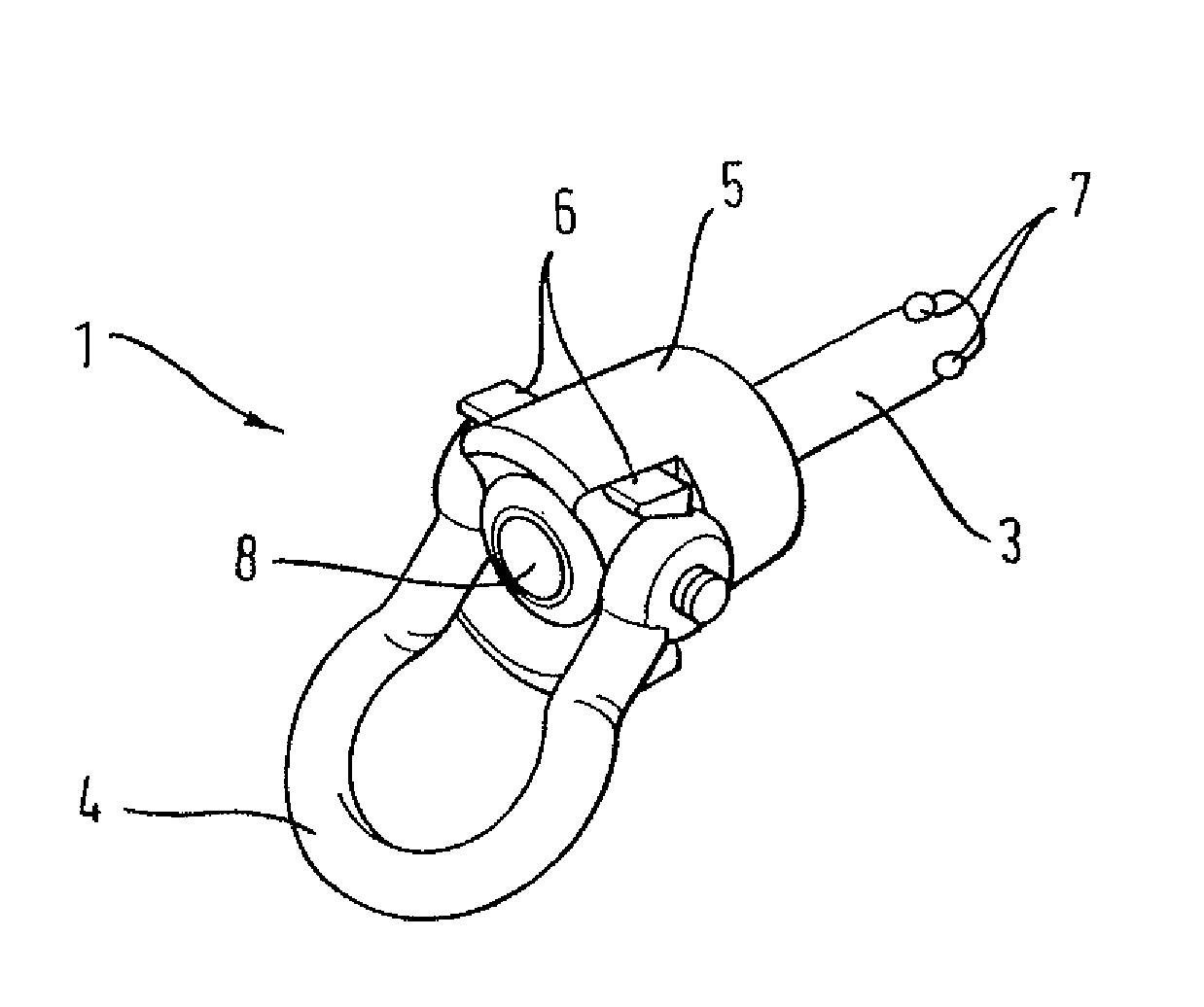
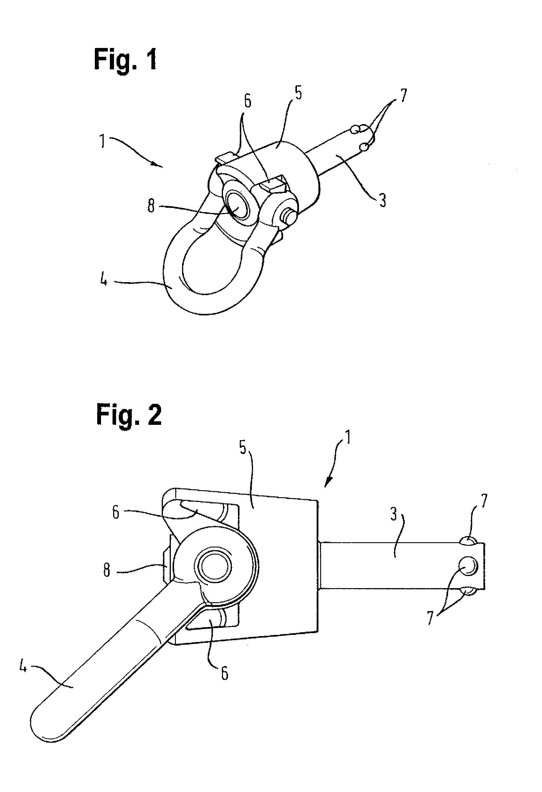
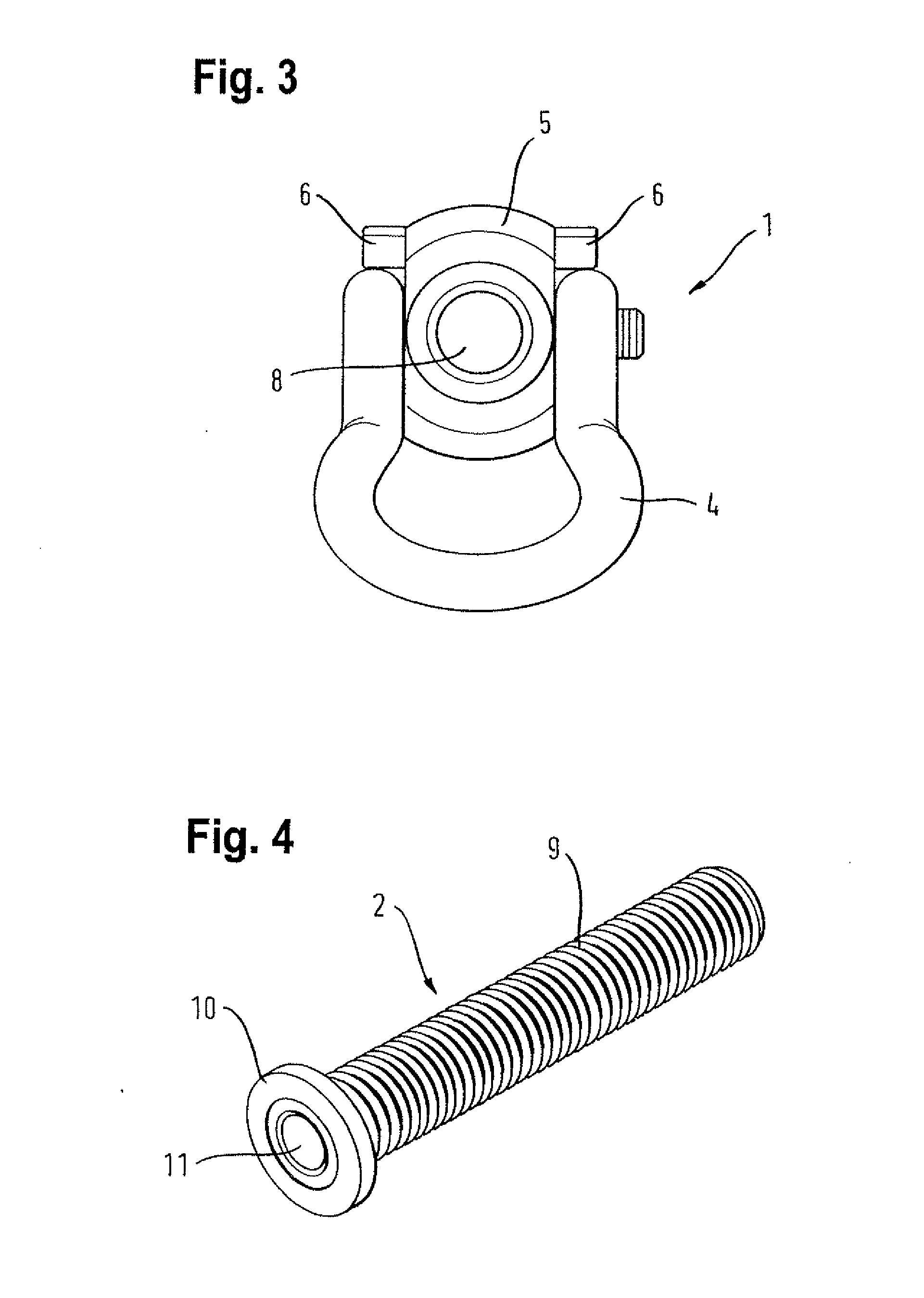
[0021]The idea on which the invention is based is that, in the case of a securing system whose securing eye is designed to have a spigot and a securing ring which is mounted to be pivotable relative thereto, the risk of damage to or dirtying of a wall of a building caused by contact with a carabiner fastened to the securing ring can be effectively and easily avoided by limiting the angular range of pivot of the securing ring to less than 180° (and in particular to less than ±90° from the co-axial alignment of the securing ring relative to the spigot). In this way, the advantages of a securing ring of a securing eye where the securing ring is mounted to be pivotable on the spigot, namely the assurance that the securing ring will always be correctly loaded, can be combined with the advantage of a design where the securing eye is not movable, namely that there is less risk of damage to or dirtying of a wall of a building.

[0022]Provision is preferably made for the angular range of pivot...


PUM


Abstract

A securing lug having a bolt and a securing ring which is connected pivotably to the bolt, as a result of which the pivoting-angle range of the securing ring is limited to less than 180°.

Description

BACKGROUND OF THE INVENTION[0001]1. Field of the Invention[0002]The invention relates to a securing eye or lug to form a releasable attachment point and to a securing system which comprises a securing eye of this kind.[0003]2. Description of Related Art[0004]Detachable attachment points are used where persons need to work under secure conditions at a considerable height, e.g., when cleaning the outsides of windows on large buildings. A securing system which is referred to as a detachable attachment point may, in this case, comprise a plurality of anchoring elements which are solidly anchored into the outside wall of the building in various positions and which serve to receive, in such a way that it can be released, a securing eye which the person to be secured inserts, as required, in the particular anchoring element involved. The person is then able to secure himself to this securing eye by means of a carabiner for example. The principal advantage of an attachment point which, rath...

Claims


Application Information

Patent Timeline
IPC IPC(8): F16B45/00
CPCF16B45/00A62B35/0068F16B19/109F16B45/002F16B45/005
Inventor RINKLAKE, KAI
Owner SKYLOTEC GMBH
Why Eureka
Try Eureka