Vehicle system

a technology of vehicle system and charging position, applied in the field of vehicle system, to achieve the effect of easily and reliably bringing into the charging position

Active Publication Date: 2014-08-07
LELY PATENT
View PDF3 Cites 23 Cited by
  • Summary
  • Abstract
  • Description
  • Claims
  • Application Information

AI Technical Summary

Benefits of technology

[0010]It is an object of the invention to provide a vehicle system wherein the respective power inlet and outlet co

Problems solved by technology

Even with sophisticated guiding systems it remains a challenge to provide a system that allows for easy, efficient and particula

Method used


Image

  • Vehicle system
  • Vehicle system
  • Vehicle system

Examples


Embodiment Construction

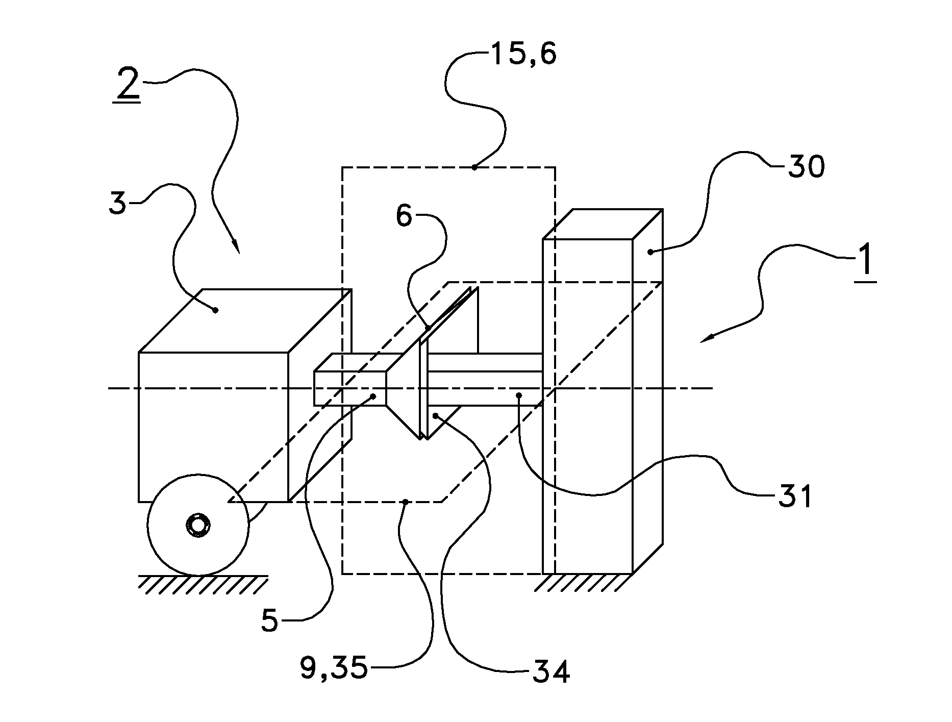
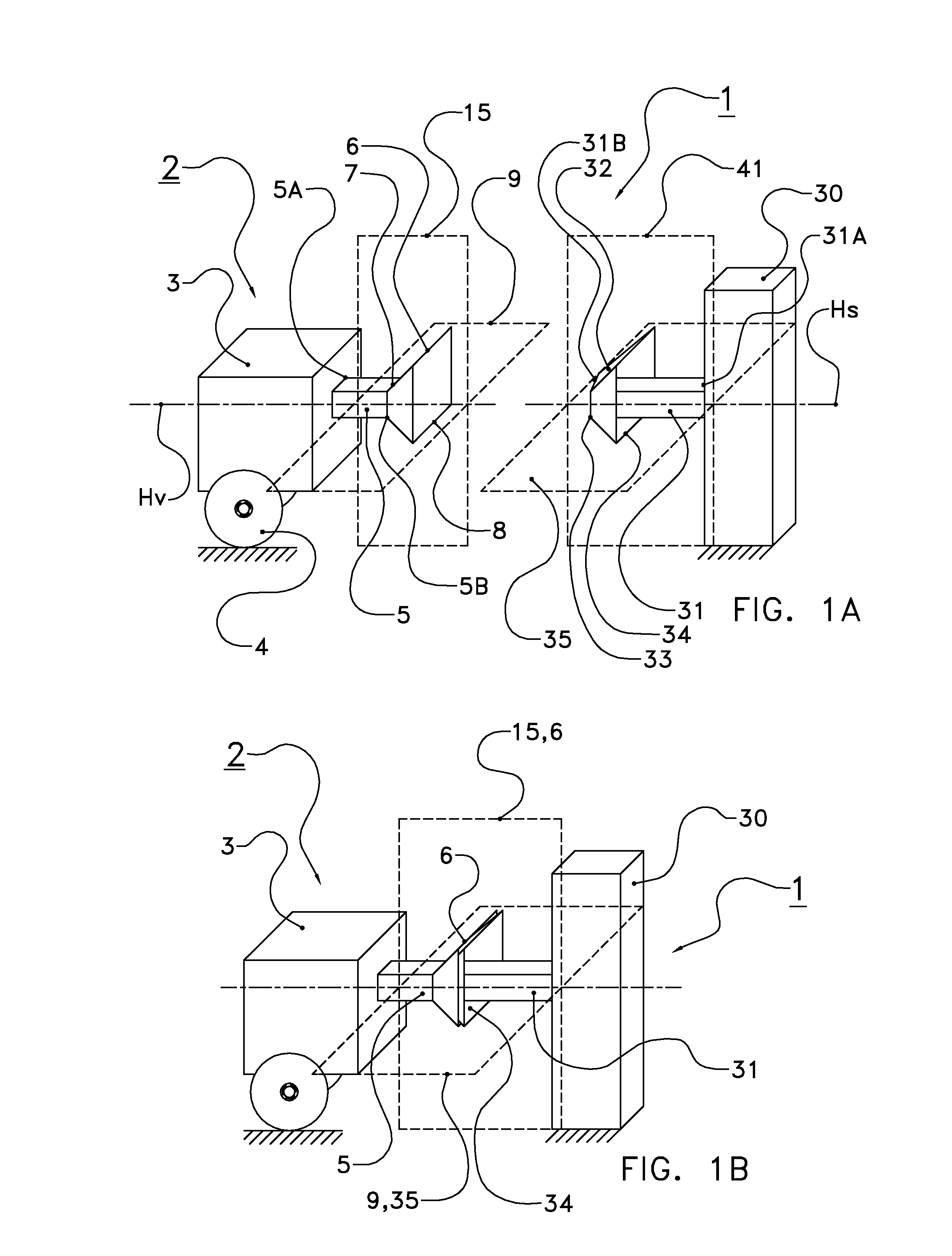
[0047]The following is a description of certain embodiments of the invention, given by way of example only and with reference to the drawings. FIG. 1A shows the vehicle system 1 of the invention with vehicle 2 and charging station 30. Vehicle 2 is an autonomously movable, electrically driven vehicle and is dockable with charging station 30. Vehicle 2 is shown in FIG. 1A as being at a distance from charging station 30. FIG. 1B shows vehicle 2 docked to the charging station 30.

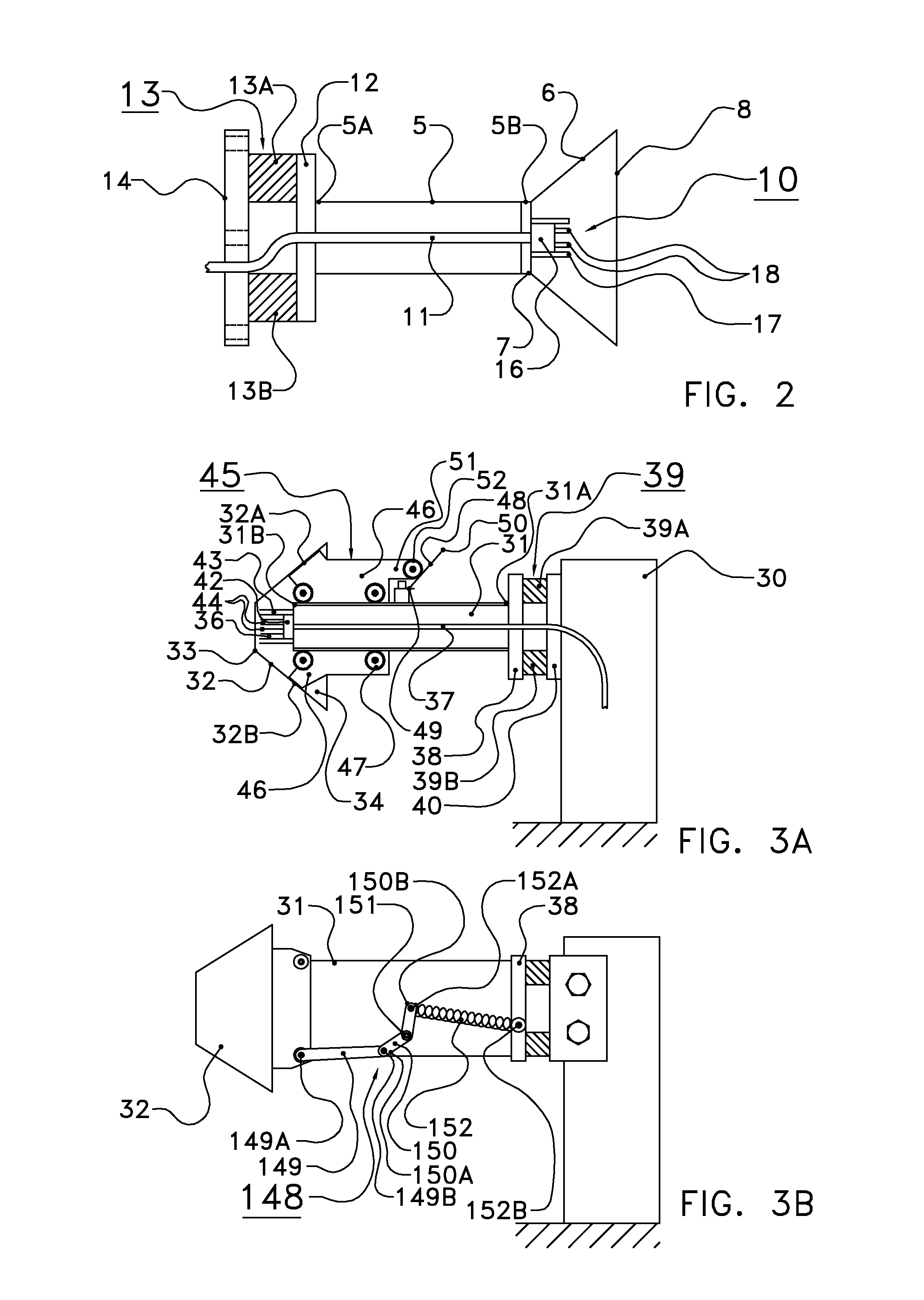
[0048]Vehicle 2 is an autonomously movable electrically powered vehicle and can move around by wheels driven by an electrical motor. The power in the vehicle is stored in onboard rechargeable batteries. An inlet side coupling means 5, 6 (explained below) is provided on vehicle 2 to facilitate docking with an outlet-side coupling means 31,32 on the charging station, explained below. Both coupling means are, when mutually engaged, arranged to transport energy from the charging station to the batteries to charge th...


PUM


Abstract

A vehicle system with a charging station and an autonomously movable, electrically powered vehicle dockable therewith, the vehicle system being mutually engageable at an inlet-side on the vehicle and an outlet-side on the charging station arranged to transport energy between the charging station and vehicle when engaged and further being provided with an inlet-side guiding member, an outlet-side guiding member, respectively, arranged to guide the inlet-side and outlet-side engagements from a non-charging position into a charging position upon engaging of the inlet- and outlet-sides when docking the vehicle to the charging station.

Description

CROSS REFERENCE TO RELATED APPLICATIONS[0001]This application is a continuation of PCT application number PCT / NL2012 / 050642 filed on 13 Sep. 2012, which claims priority from NL application number 2007566 filed on 11 Oct. 2011. Both applications are hereby incorporated by reference in their entireties.BACKGROUND OF THE INVENTION[0002]1. Field of the Invention[0003]The invention relates to a vehicle system comprising at least one charging station and at least one autonomously movable, electrically powered vehicle dockable therewith, the vehicle including an inlet-side coupling device and the charging station including an outlet-side coupling device, said inlet-side coupling device and said outlet-side coupling device being mutually engageable and arranged to transport energy between the charging station and vehicle when engaged, said inlet-side coupling device and said outlet-side coupling device further being provided with an inlet-side guiding member, an outlet-side guiding member, ...

Claims


Application Information

Patent Timeline
IPC IPC(8): B60L11/18
CPCB60L11/1833B60L53/16B60L53/35B60L53/36Y02T10/7072Y02T90/14Y02T10/70Y02T90/12
Inventor PASTOOR, JAN LAMBERTUSSIE, HOWARDVAN DEN BERG, KAREL
Owner LELY PATENT
Why Eureka
Try Eureka