Communication terminal and encoding rate reduction method

a technology of encoding rate and communication terminal, applied in the field of communication terminal, can solve problems such as image error, packet loss, wireless communication quality, etc., and achieve the effect of reducing the probability of packet loss

Active Publication Date: 2014-08-07
PANASONIC INTELLECTUAL PROPERTY MANAGEMENT CO LTD
View PDF7 Cites 17 Cited by
  • Summary
  • Abstract
  • Description
  • Claims
  • Application Information

AI Technical Summary

Benefits of technology

[0013]According to the present invention, it is possible to reduce the

Problems solved by technology

With a decrease in wireless communication quality (for example, in JP-A-2011-82837, an error rate), when a wireless transmission rate which is usable for transmission of image data decreases, it is considered that the amount of data packets of encoded image data to be stored in a buffer increases while a high image encoding rate is mainta

Method used


Image

  • Communication terminal and encoding rate reduction method
  • Communication terminal and encoding rate reduction method
  • Communication terminal and encoding rate reduction method

Examples


Embodiment Construction

[0028]First, prior to describing an embodiment of a communication terminal and an encoding rate reduction method according to the present invention, the above-described problem in the related art will be described in detail referring to FIGS. 12 and 13. FIG. 12 is a graph showing an image encoding rate on a transmission side before and after the time tHO. FIG. 13 is a graph showing the amount of data packets which are accumulated in a buffer on a transmission side before and after the time tHO. In FIGS. 12 and 13, the time tHO is the time at which an inter-RAT handover procedure ends, and it is assumed that a communication protocol A (for example: LTE) is switched to a communication protocol B (for example: HPSA) at the time tHO.

[0029]A maximum transmission rate allocated to a terminal on a transmission side decreases from a maximum transmission rate corresponding to the communication protocol A to a maximum transmission rate corresponding to the communication protocol B by inter-RA...


PUM


Abstract

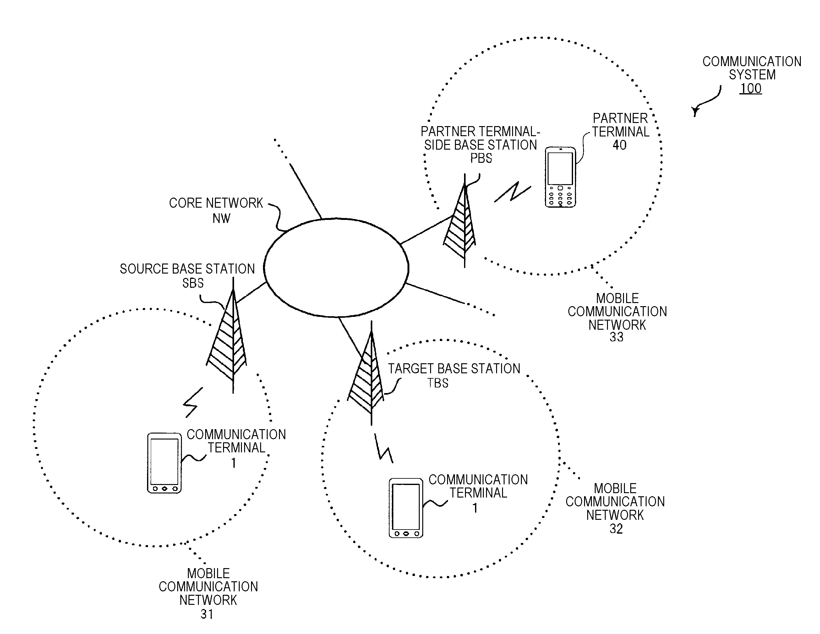
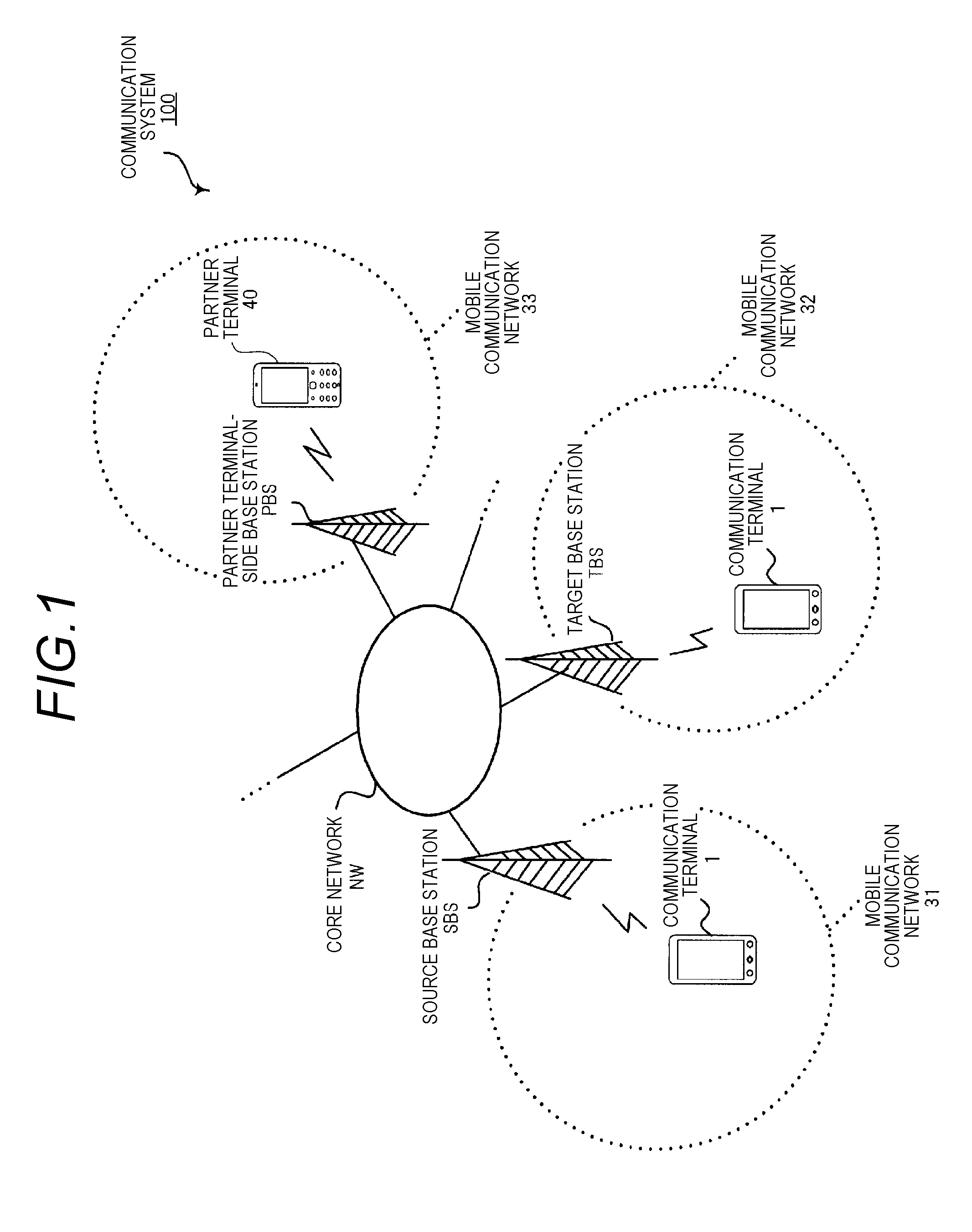
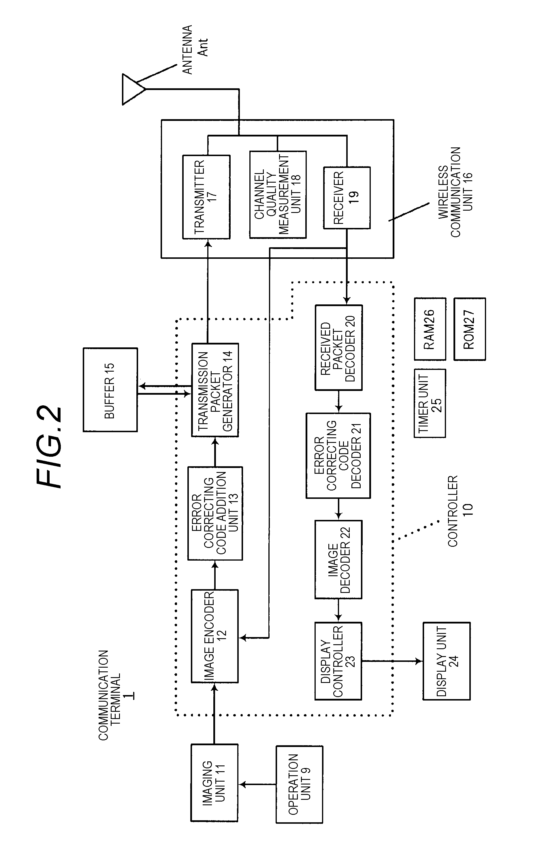
A communication terminal includes a communication unit to be connected to a first base station and a second base station in different communication protocols, and an encoder which encodes data at an encoding rate determined according to the first base station or the second base station for each predetermined time T and outputs the encoded data to the communication unit. When a connection destination is changed from the first base station to the second base station in a period when the communication unit is being connected to the first base station, the communication unit transmits change information to the encoder before the change of the connection to the second base station is completed. The encoder changes the encoding rate determined according to the first base station to the encoding rate determined according to the second base station when received the change information.

Description

BACKGROUND[0001]1. Field of the Invention[0002]The present invention relates to a communication terminal which is connectable to a plurality of base stations, and an encoding rate reduction method in the communication terminal.[0003]2. Description of the Related Art[0004]In recent years, in a cellular mobile communication network, with multimedia of information, in order to implement large-capacity data transmission, a technique which uses wireless communication in a high frequency band to implement a high transmission rate (communication speed) is actively studied.[0005]In the cellular mobile communication network, for example, there are an LTE (Long Term Evolution) protocol, a W-CDMA (Wideband Code Division Multiple Access) protocol or a CDMA2000 protocol classified into 3G (3rd Generation), an HSPA (High Speed Packet Access) protocol classified into 3.5G, and a GSM (Registered Trademark) (Global System for Mobile Communication) protocol classified into 2G (2nd Generation). In the...

Claims


Application Information

Patent Timeline
IPC IPC(8): H04W36/02
CPCH04W36/023H04W36/0066
Inventor KATO, OSAMU
Owner PANASONIC INTELLECTUAL PROPERTY MANAGEMENT CO LTD
Why Eureka
Try Eureka