Air cooling system for an unmanned aerial vehicle

a technology for air cooling systems and unmanned aerial vehicles, which is applied in the direction of machines/engines, mechanical equipment, transportation and packaging, etc., can solve the problems of overcooling affecting the operation of conventional uav engines, and the engine operation problems of overcooling, so as to minimise the effect of propeller efficiency and maximising the draw of cooling air

Active Publication Date: 2014-08-07
ORBITAL ENGINE CO PTY LTD
View PDF2 Cites 12 Cited by
  • Summary
  • Abstract
  • Description
  • Claims
  • Application Information

AI Technical Summary

Benefits of technology

[0012]The air is conveniently supplied, during operation of the prop, through a cooling air duct for cooling the engine of the unmanned aerial vehicle (UAV), air cooled engines being advantageous from perspectives of minimizing weight, failure modes and cost of the aircraft. A single cooling air duct may be provided for directing air at a selected portion of the engine for cooling. However, the cooling air duct may have plural portions, or plural cooling air ducts may be provided, to direct cooling air wherever required for the engine. Engine cooling air must be supplied in a controlled manner because, whilst engine overheating would be a real risk prior to launch, the opposite problem of overcooling can impact conventional UAV engines during descent and other potential modes of engine operation. That is, overcooling creates its own engine operability problems.
[0029]One or more embodiments includes the outlet adjacent the propeller arranged and located to maximise the draw of cooling air through the shroud or cowling, such as through the distance from the propeller itself and the axis of propeller rotation, while minimising any effects on propeller efficiency.

Problems solved by technology

Engine cooling air must be supplied in a controlled manner because, whilst engine overheating would be a real risk prior to launch, the opposite problem of overcooling can impact conventional UAV engines during descent and other potential modes of engine operation.
That is, overcooling creates its own engine operability problems.

Method used


Image

  • Air cooling system for an unmanned aerial vehicle
  • Air cooling system for an unmanned aerial vehicle
  • Air cooling system for an unmanned aerial vehicle

Examples


Embodiment Construction

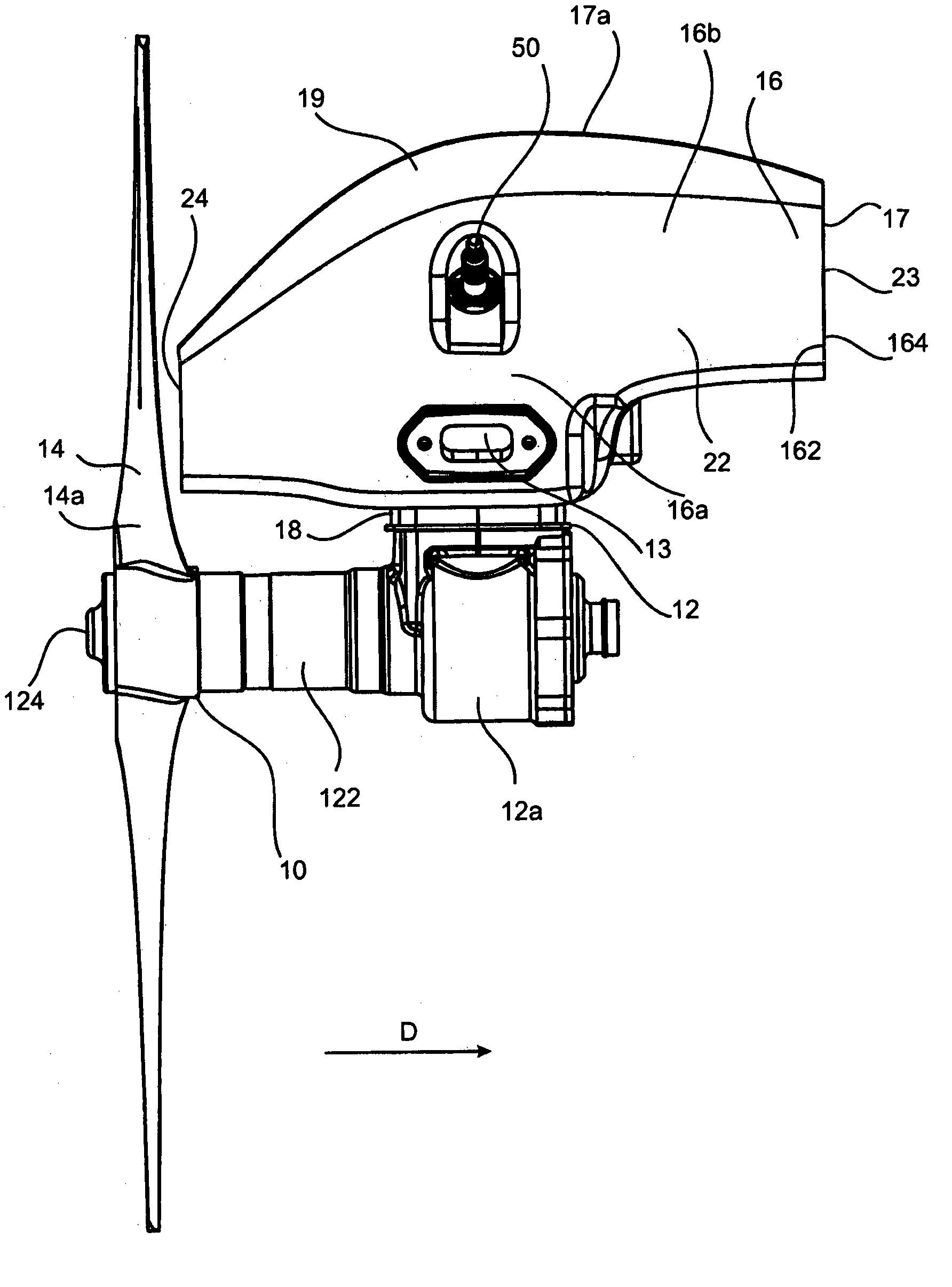
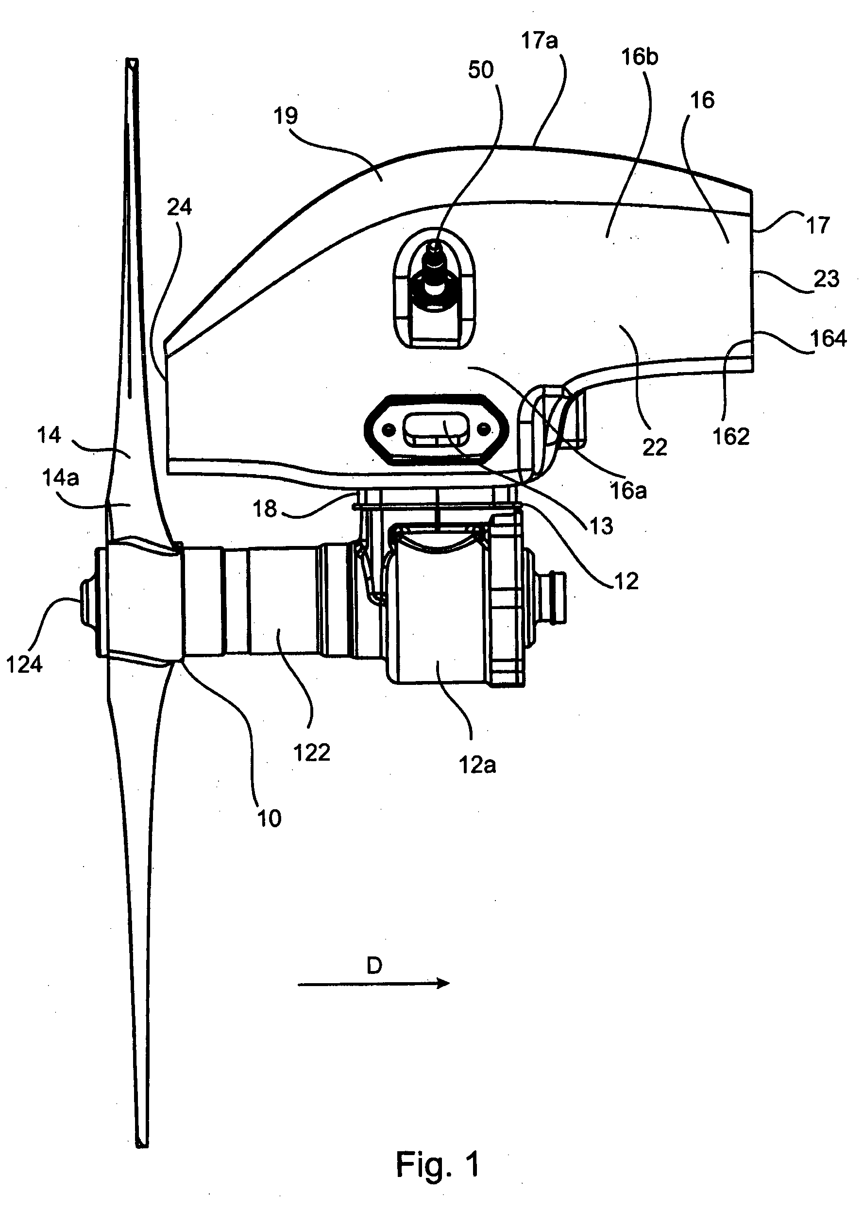
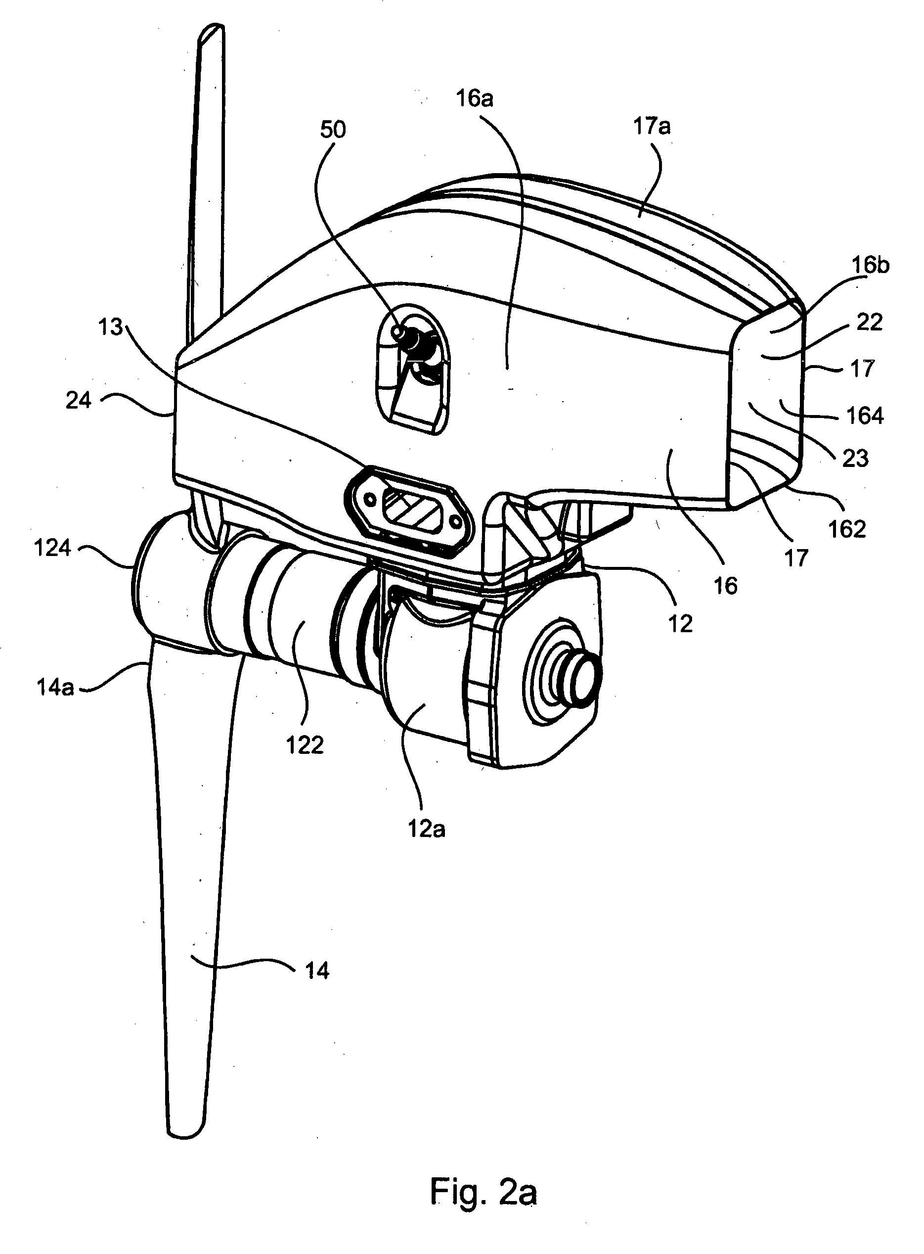
[0042]Referring first and generally to FIGS. 1 to 8, an unmanned aerial vehicle (UAV) (not shown), e.g. to be launched by a catapult launcher, includes a pusher prop assembly 10 driven by an engine 12, a lower part 12a of which is visible. Lower part 12a of engine 12 includes a casing 122 for a drive shaft 124 engaging engine 12 with prop 14 of conventional design.

[0043]The engine 12 is a two stroke fuel injected engine provided with a dual fluid fuel injection system as supplied by Orbital Engine Corporation Ltd under the trade mark “FlexDI”. Fuel is ignited by spark plug 50 and exhaust gases from combustion are exhausted through exhaust port 13.

[0044]The upper part of engine 12 is partially enclosed by an engine cowl 16, the engine cooling cowl 16 being arranged in close alignment with the cylinder head 18 (as shown in FIG. 9). Engine cowl 16 comprises a cylinder head portion 16a surrounding the cylinder head 18; and a plenum portion 16b, defined by side walls 17 connected by an u...


PUM


Abstract

An air cooling system for an unmanned aerial vehicle including a propeller (14) driven by an engine (12) has at least one cooling air duct (22) to direct cooling air to cool a vehicle component e.g. a cylinder head. The duct has at least one air inlet and at least one air outlet. Operation of the propeller causes a pressure differential between the air outlet (24,124) and the air inlet (23,123) which draws air through said cooling air duct (22). A cowling (16) can cover at least part of the engine, and can form a plenum and have the supply of cooling air through a front face aperture (164) or side walls (17) of the engine cowl (16).

Description

TECHNICAL FIELD[0001]This invention relates to an air cooling system for an unmanned aerial vehicle (“UAV”).BACKGROUND[0002]UAVs have increasing application for defence and security applications being used for many purposes including surveillance and harassment. However, UAVs may be used for a range of other purposes in civil applications including surveying and mineral exploration.[0003]Various designs of UAV are in current use. Some are of ducted fan type in which a rotary fan, propeller or prop assembly, driven by an engine, is enclosed within a shroud. Others are of fixed wing type or helicopter type and still others are of hybrid type such as described in U.S. Pat. No. 6,270,038 assigned to Sikorsky Aircraft Corporation.[0004]UAV engines like other engines require a cooling system to ensure satisfactory engine operation and to prevent overheating and potential failure associated therewith.[0005]Air cooling of UAV engines is preferred, where possible, since this reduces the over...

Claims


Application Information

Patent Timeline
Patent Type & Authority Applications(United States)
IPC IPC(8): F01P1/06
CPCF01P1/06B64C39/024B64D33/08F01P1/02F01P2050/20B64U50/11
Inventor BLEECHMORE, CALLAN MURRAYTUBB, JOHN HOWARDRAILTON, DONALD ANDREWKARAY, STEPHEN JOHNMEHRANI, POURIA
Owner ORBITAL ENGINE CO PTY LTD
Why Eureka
Try Eureka