
Foam Reinforced Structural Member

a technology of reinforced structural members and foam, which is applied in the field of composite materials and methods for reinforcing closed structural members, can solve the problems of high material and weight loss, high cost of techniques, and inability to achieve material and weight reduction, so as to maximize weight savings, reduce overall cost, and optimize the strength and weight of reinforced structural members

Inactive Publication Date: 2014-08-07
JOHNSON CONTROLS TECH CO
View PDF1 Cites 3 Cited by
  • Summary
  • Abstract
  • Description
  • Claims
  • Application Information

AI Technical Summary

Benefits of technology

This patent describes a method for making a stronger and lighter reinforced structural member. The method involves analyzing the forces that the frame will be subjected to and configuring the thickness of the frame to be strong enough to withstand the forces likely to occur in the least forceful parts of the frame. The composite material is used in other parts of the frame to reinforce against greater forces and stresses that will be experienced by the frame. The type, density, and location of the composite material are selected to prevent failure of the frame and maximize weight savings. The cure time of the composite material is also considered to ensure all forming operations are completed before the material hardens. Overall, this method provides a way to make stronger and lighter reinforced structural members.

Problems solved by technology

More specifically, certain areas of the frame experience higher loads and stresses than other areas.
While some techniques, such as using special alloys or, to a limited extent, variable wall thickness have been used, these techniques are expensive.
In addition, the areas of the seat frame, other than those experiencing the minimum stress or load, have not successfully been reduced in material and weight while maintaining desired performance characteristics and maintaining or reducing cost of the seat frame.
Given the density of the polyurethane foam, the limited additional strength added, additional weight in many instances, and increased cost, these polyurethane filled tubes have had only limited success.

Method used


Image

  • Foam Reinforced Structural Member
  • Foam Reinforced Structural Member
  • Foam Reinforced Structural Member

Examples


Embodiment Construction

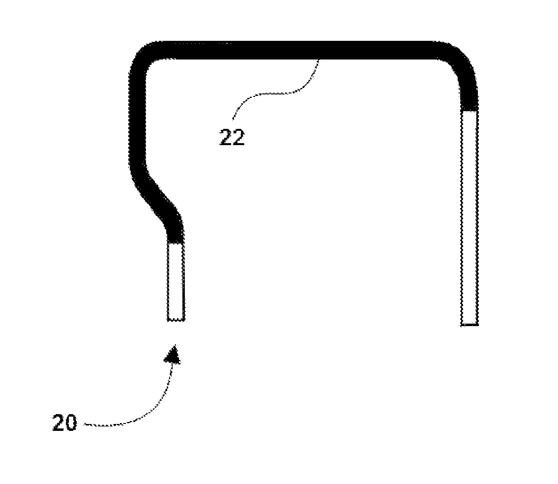
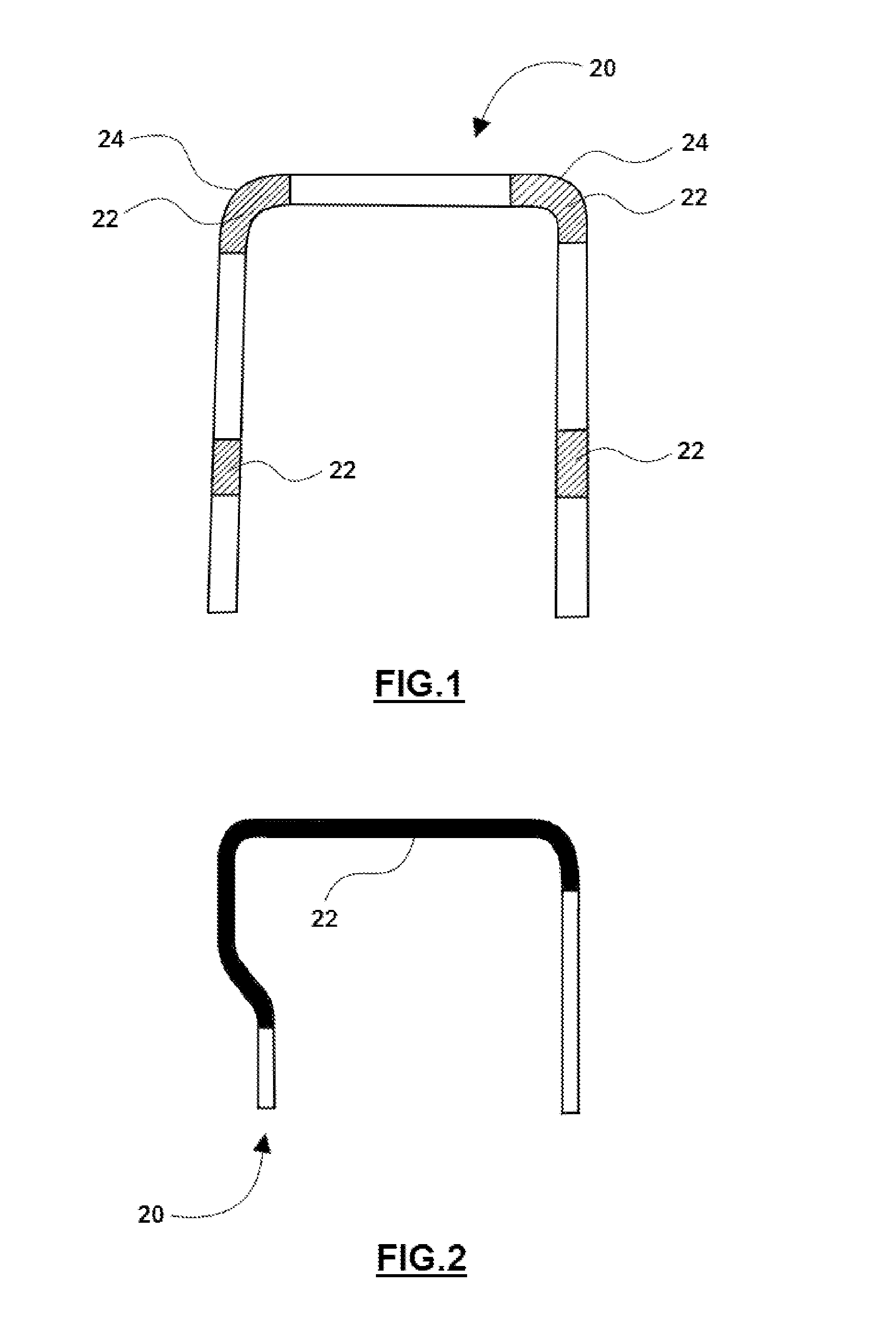
[0021]Referring to the Figures, wherein like numerals indicate corresponding parts throughout the several views, a structural member such as a tube 20 forming a seat frame is generally shown in FIGS. 1 and 2, as an upper seat frame reinforced with the composite material 22. The structural member or tube 20 of the exemplary embodiment is illustrated in the Figures as a back frame structure for a vehicle seat. However, it should be appreciated that the structural member 20 could be used in a wide range of other applications. For example, the structural member may be used for vehicle body stiffness and offset barrier performance for pillars and rails, as well as improved side impact performance in door bolsters. Additionally, the structural member 20 of the exemplary embodiment as illustrated in the Figures typically has a circular shape when viewed in cross-section; however, the structural member 20 could have any desirable cross-sectional shape, and the cross-section could vary along...


PUM

PropertyMeasurementUnit
Fractionaaaaaaaaaa
Fractionaaaaaaaaaa
Fractionaaaaaaaaaa

Abstract

A composite material for reinforcing closed structural members as a tube or any closed profile section. More specifically, a composite material for filling metal tubes or any closed profile section forming the frame of vehicle seats to increase or maintain the strength of the seat frame while reducing the mass of the seat tubes or sealed profile section.

Description

CROSS-REFERENCE TO PRIOR APPLICATIONS[0001]This U.S. National Stage patent application claims priority to International Application Serial No. PCT / US2012 / 047291 filed Jul. 19, 2012 entitled “Foam Reinforced Structural Member,” which claims the benefit of U.S. Provisional Patent Application Ser. No. 61 / 509,239 filed Jul. 19, 2011, entitled “Foam Reinforced Structural Member,” the entire disclosures of the applications being considered part of the disclosure of this application and hereby incorporated by reference.BACKGROUND OF THE INVENTION[0002]1. Field of the Invention[0003]The invention is generally directed to a composite material and method for reinforcing closed structural members, such as tubes or any member having a substantially closed profile section. More specifically, the invention is directed to a composite material and method for filling metal tubes or any member with a closed profile section, such as the tubes that form the frame of vehicle seats, to increase or mainta...

Claims


Application Information

Patent Timeline
IPC IPC(8): C08L75/04
CPCC08L75/04C08G18/00C08G18/5021C08G18/7657C08G18/48C08K7/24C08G18/4854C08G18/6511C08G18/6705C08G18/3206C08G2110/0083
Inventor MCEVOY, JAMES T.MCCLARREN, PATRICIA J.BALIN, ALEXANDER I.THOMAS, MICHAEL J.
Owner JOHNSON CONTROLS TECH CO
Learn More