Method for assembling a nozzle and an exhaust case of a turbomachine

a technology of exhaust case and nozzle, which is applied in the field of turbomachines, can solve the problems of significant restrictions in the lifetime (or service life) of the exhaust case, and achieve the effect of enhancing the life of the exhaust case and less restrictive in operation

Active Publication Date: 2014-02-27
SN DETUDE & DE CONSTR DE MOTEURS DAVIATION S N E C M A
View PDF17 Cites 15 Cited by
  • Summary
  • Abstract
  • Description
  • Claims
  • Application Information

AI Technical Summary

Benefits of technology

[0009]Therefore there is a need to provide a new method for assembling a nozzle to the exhaust case of a turbomachine enabling the lifetime of the exhaust case to

Problems solved by technology

Consequently, this design known in prior art for attaching the mixer M to the exhaust case C results in that the attachment flange 3“drives” the displacements of the outer ferrule 5 at the arms 6, and thus, by a flexure effect, impacts t

Method used


Image

  • Method for assembling a nozzle and an exhaust case of a turbomachine
  • Method for assembling a nozzle and an exhaust case of a turbomachine
  • Method for assembling a nozzle and an exhaust case of a turbomachine

Examples


Embodiment Construction

[0050]Throughout the description, by “axial flange”, respectively “radial flange”, it is intended a flange associated with an axial, respectively radial bolted joint.

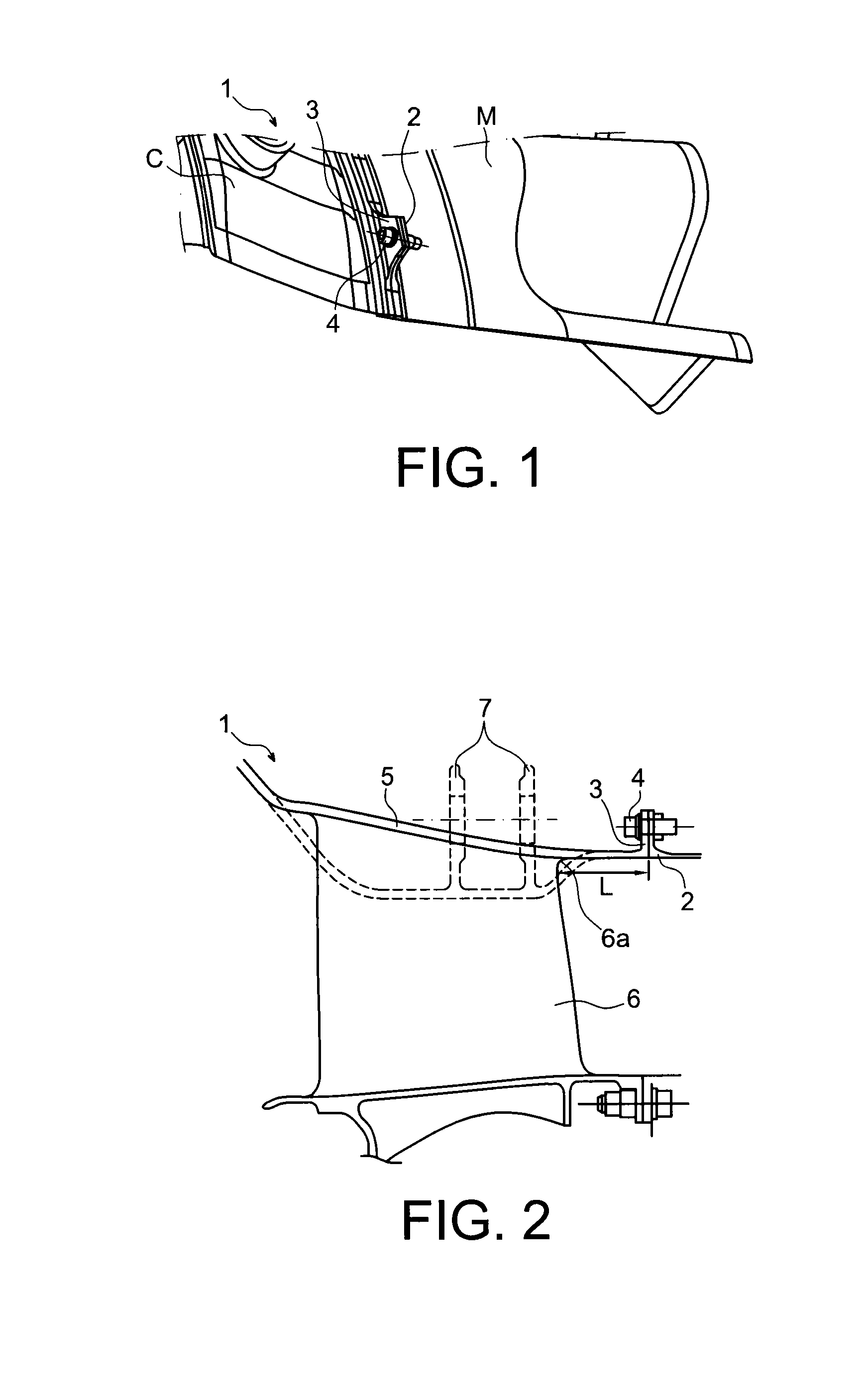
[0051]It will now be described hereinafter, in reference to FIGS. 3 to 7, an exemplary exhaust system including a nozzle and an exhaust case assembled by implementing the method according to the invention.

[0052]In this example, the nozzle includes a mixer M, and the assembly of the nozzle to the exhaust case C includes the assembly of the mixer M to the exhaust case C. On the other hand, the attachment mode represented in a radial attachment mode, through radial attachment flanges, but this choice is in no way limiting. Alternatively, the attachment of the exhaust case C and the mixer M can be made by means of axial attachment flanges.

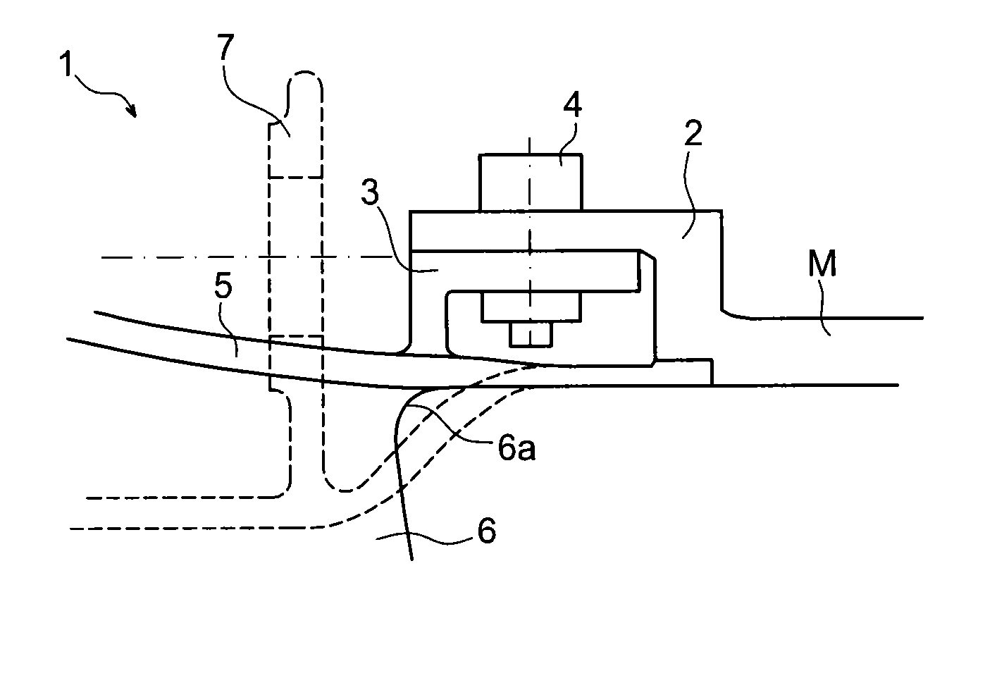
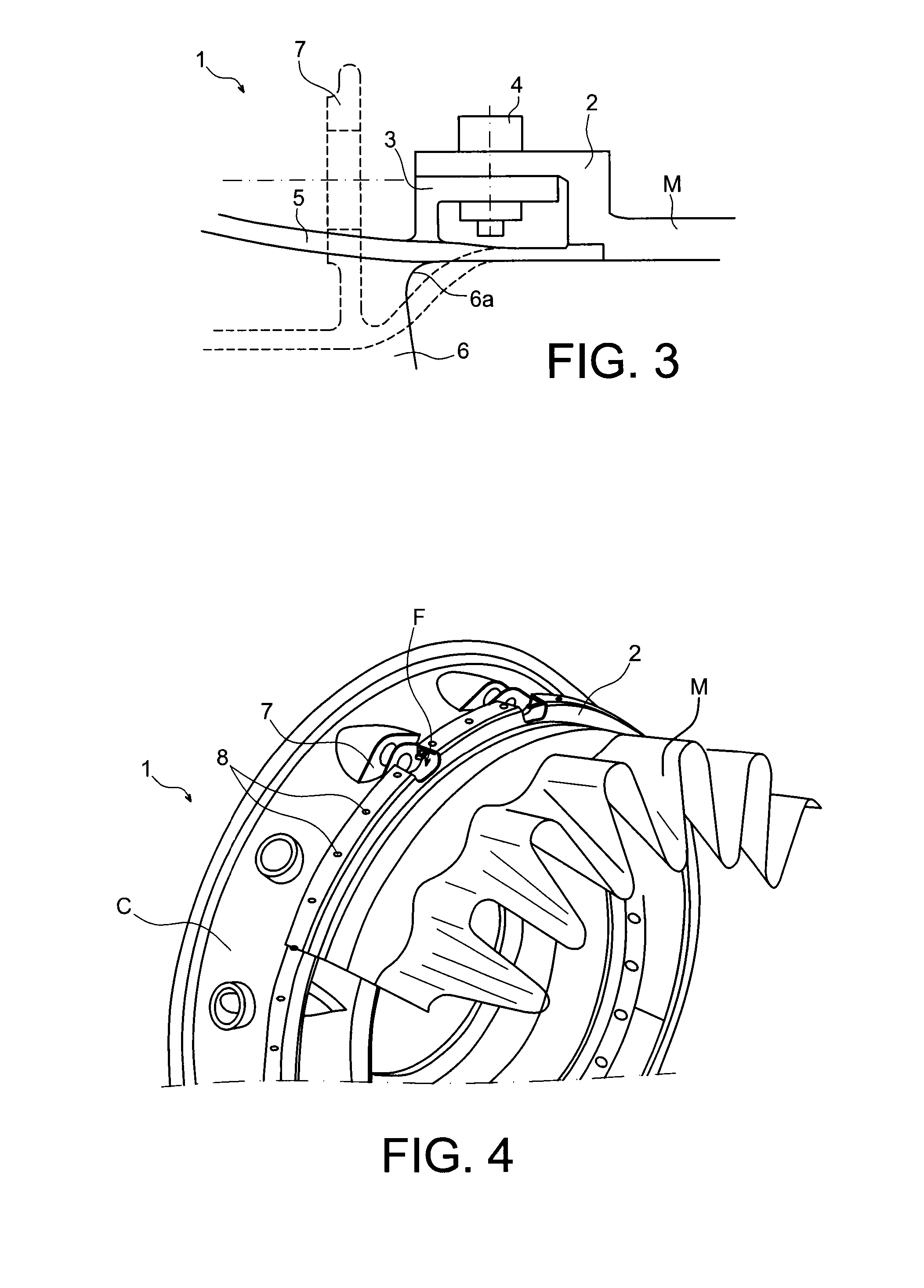
[0053]FIG. 3 represents, in a schematic cross-section view, the attachment between the mixer M and the outer ferrule 5 of the exhaust case C according to the method in accordance with the ...


PUM


Abstract

A method for assembling a nozzle and an exhaust case of a turbomachine is disclosed. The exhaust case includes a hub and an outer ferrule connected to each other by a plurality of arms. The nozzle is attached to the outer ferrule of the exhaust case substantially at the trailing edges of the arms.

Description

TECHNICAL FIELD[0001]The present invention relates to the field of turbomachines, and more particularly to the field of exhaust cases and nozzles equipping turbomachines. It relates to a method for assembling a nozzle and an exhaust case of a turbomachine, an exhaust system including such a nozzle and such an exhaust case, as well as the associated turbomachine.[0002]The invention is applicable to any type of terrestrial or aeronautic turbomachines, and in particular to aircraft turbomachines such as turbojet engines and turboprop engines. More preferentially, the invention can be applied to a twin spool turbofan engine.STATE OF PRIOR ART[0003]In the field of turbomachines, the nozzle is the variable cross-section duct placed on the exhaust case at the outlet of the combustion chamber for transforming the energy of combustion gases into kinetic energy.[0004]Separate flow nozzles can in particular be mentioned, which generally consist of a confluent flow nacelle enclosing a primary c...

Claims


Application Information

Patent Timeline
IPC IPC(8): F02C7/20
CPCF02C7/20F01D9/065F01D25/162F01D25/243F01D25/30F02K1/80F05D2230/60Y02T50/60Y10T29/49321F02K1/386F02K1/48
Inventor DE SOUSA, MARIO CESARACHBARI, BAGHDADDAGUENET, LUC HENRI CLAUDEDEBRAY, BENOIT
Owner SN DETUDE & DE CONSTR DE MOTEURS DAVIATION S N E C M A
Why Eureka
Try Eureka