
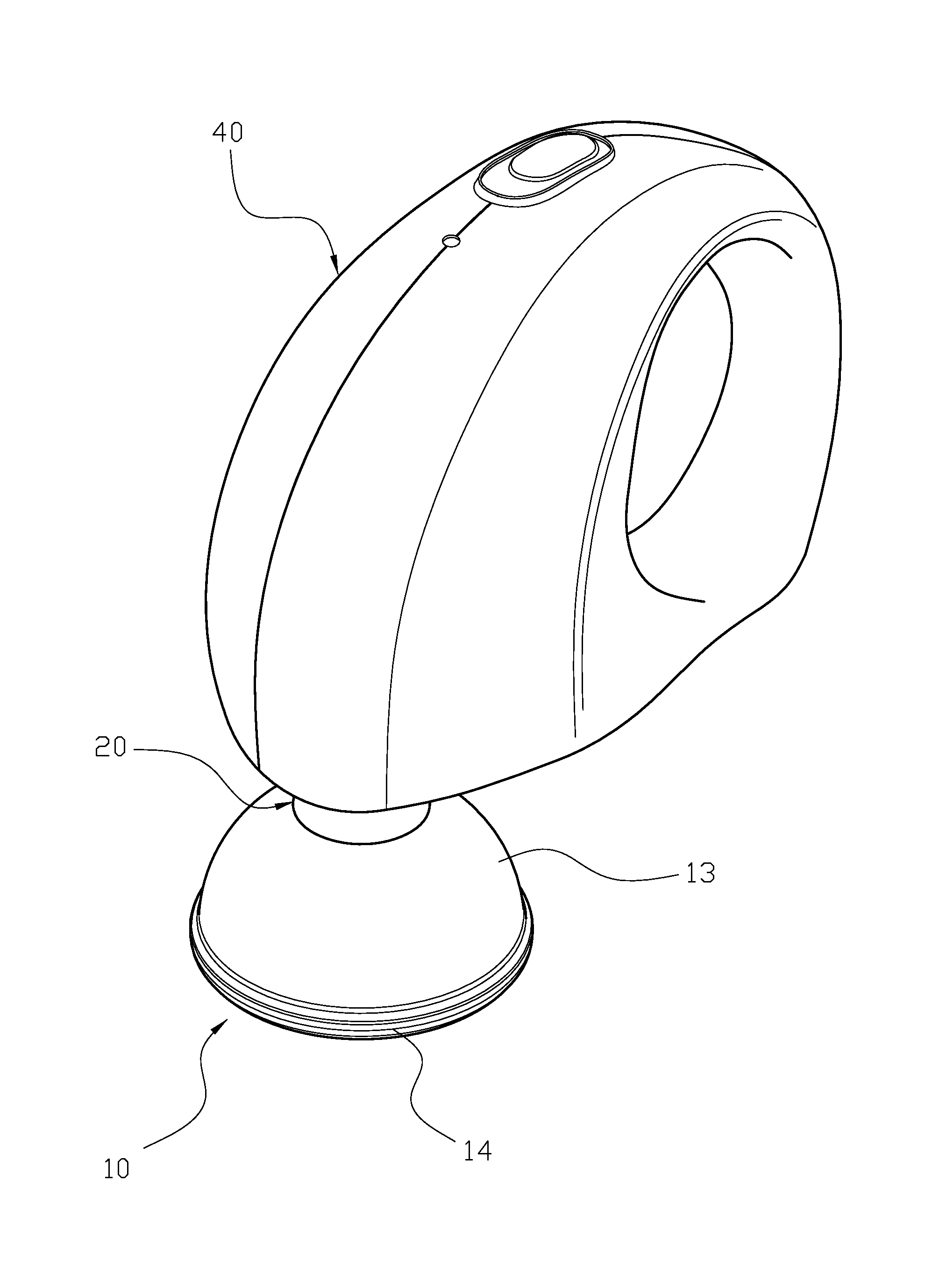
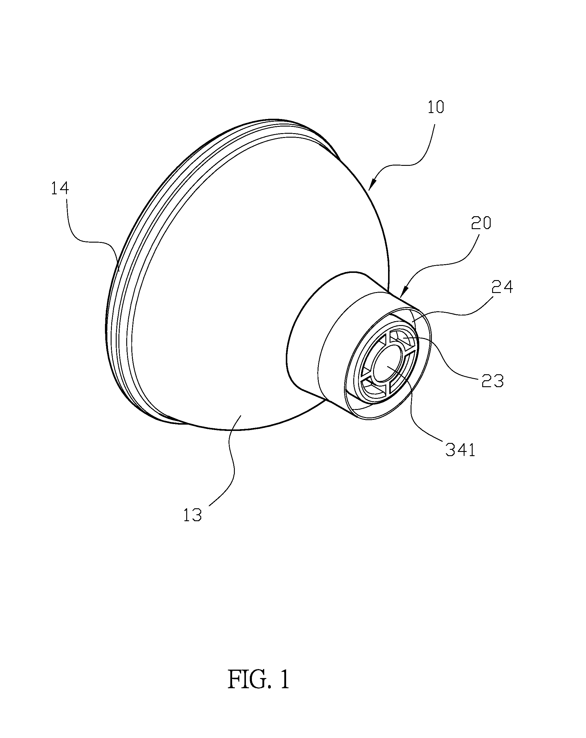
Positioning structure of plastic disk of massaging device

a technology of massaging device and plastic disk, which is applied in the field of massaging device, can solve the problems of increasing the wear inside the rotating unit, the connection between the massaging cover and the rotating unit may be too tight, and the disadvantages of the conventional massaging device, and achieves the effect of convenient replacemen

Inactive Publication Date: 2014-08-07
WU DONG HER
View PDF26 Cites 40 Cited by
  • Summary
  • Abstract
  • Description
  • Claims
  • Application Information

AI Technical Summary

Benefits of technology

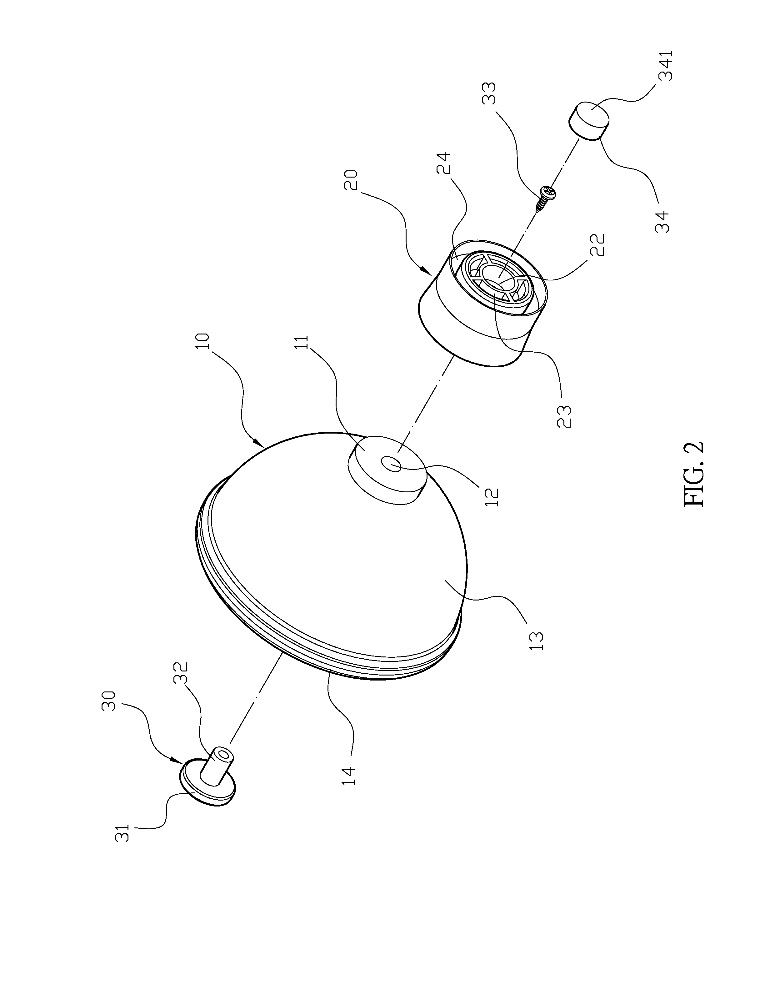
The present invention provides a driving device and a connecting unit for massaging units which can quickly and securely engage each other. The driving device has a rotating shaft with positioning pieces that can easily plug into the connecting unit's positioning slots. A stopping block on the positioning piece engages with a receiving space in the connecting unit to quickly connect the two units. The connecting unit has a fixed hole with a ring slot and a restricting ring to prevent excess bending of the positioning piece. The screw secures the massaging unit and connecting unit to prevent them from falling off. The restricting ring also prevents overbending of the positioning piece.

Problems solved by technology

However, the conventional massaging device is disadvantageous because (i) the massaging cover is connected with a connecting unit and a rotating plate that has a polygonal hole.
Although it results a quick assembly and disassembly, the connection between the massaging cover and the rotating unit may be too tight if the polygonal hole is too small, while the massaging cover may fall off if the polygonal hole is too large; (ii) the massaging cover has a ladder-shaped hole and the driving unit has a through hole, and a securing unit is used to pass through the ladder-shaped hole and through hole.
When the massaging cover is conducting massaging activities, the massaging cover may generate a lateral force to the driving unit, so the securing unit may not be securely engaged with the driving unit; and (iii) since the rotating unit is connected with the massaging cover only through the shaft's insertion into the polygonal hole, when the massaging cover is conducting massaging activities, a lateral force is generated to the shaft to break the driving unit and further increase the wear inside the rotating unit.

Method used


Image

  • Positioning structure of plastic disk of massaging device
  • Positioning structure of plastic disk of massaging device
  • Positioning structure of plastic disk of massaging device

Examples


Embodiment Construction

[0017]The detailed description set forth below is intended as a description of the presently exemplary device provided in accordance with aspects of the present invention and is not intended to represent the only forms in which the present invention may be prepared or utilized. It is to be understood, rather, that the same or equivalent functions and components may be accomplished by different embodiments that are also intended to be encompassed within the spirit and scope of the invention.

[0018]Unless defined otherwise, all technical and scientific terms used herein have the same meaning as commonly understood to one of ordinary skill in the art to which this invention belongs. Although any methods, devices and materials similar or equivalent to those described can be used in the practice or testing of the invention, the exemplary methods, devices and materials are now described.

[0019]All publications mentioned are incorporated by reference for the purpose of describing and disclos...


PUM


Abstract

A positioning structure of a plastic disk in a massaging device may include a massaging unit, a connecting unit and a locking unit. The massaging unit has a protruding block that has a through hole. One end of the connecting unit has a receiving space that is used to receive the protruding block, a fixed hole of the connecting unit aligned with the through hole, and a plurality of positioning slots circularly formed at outer periphery of the fixed hole of the connecting unit. The locking unit has a head portion and a tubular unit extending from the head portion, wherein the tubular unit of the locking unit passes through the through hole and fixed hole, and a screw is used to secure the tubular unit to connect the massaging unit and the connecting unit.

Description

FIELD OF THE INVENTION[0001]The present invention relates to a massaging device, more particularly to a positioning structure of plastic disk in the massaging device.BACKGROUND OF THE INVENTION[0002]Conventional massaging devices, such as the one disclosing in Taiwanese Patent No.: M362693, titled “eccentrically rotated massaging device,” has an inner curved lip-shaped edge at an opening of a massaging cover, and the lip-shaped edge is used to touch the user's body with its resilience to increase the massaging area and further provide a comfortable massaging process. However, the conventional massaging device is disadvantageous because (i) the massaging cover is connected with a connecting unit and a rotating plate that has a polygonal hole. The rotating unit is driven by a motor with a shaft that is configured to plug into the polygonal hole. Although it results a quick assembly and disassembly, the connection between the massaging cover and the rotating unit may be too tight if th...

Claims


Application Information

Patent Timeline
Patent Type & Authority Applications(United States)
IPC IPC(8): A61H15/00
CPCA61H15/0092A61H7/005A61H7/007A61H23/0254A61H2201/1671A61H2201/1685A61H2201/1695A61H7/00A61H23/00A61H39/04
Inventor WU
Owner WU DONG HER
Learn More