Coding for real-time streaming under packet erasures

a real-time streaming and packet erasure technology, applied in the field of real-time streaming systems, can solve the problem that the code design is not explicitly optimized, and achieve the effect of reducing the expected message decoding delay

Active Publication Date: 2014-08-07
CALIFORNIA INST OF TECH
View PDF9 Cites 8 Cited by
  • Summary
  • Abstract
  • Description
  • Claims
  • Application Information

AI Technical Summary

Benefits of technology

[0008]The various embodiments according to the present disclosure consider a real-time streaming system where messages created at regular time intervals at a source are encoded for transmission to a receiver over a packet erasure link. According to some embodiments of the present disclosure, the messages created by the source are high and low priority messages according to a periodic pattern. The receiver must subsequently decode each message within a given delay from its creation time while taking into account, if applicable, a corresponding priority of the message. Unlike previous work that aim to minimize the expected message decoding delay, or achieve a decoding failure probability that decays exponentially with delay (e.g. [4]-[6] per Annex A1), the real-time streaming model according to the various embodiments of the present disclosure features hard message decoding deadlines. Novel code construction to comply with such streaming system model is presented in this disclosure, with more detailed information in Annex A1 and Annex A2 which both make part of the present disclosure.

Problems solved by technology

Furthermore, the code design is not explicitly optimized with respect to a per-message decoding delay requirement.

Method used


Image

  • Coding for real-time streaming under packet erasures
  • Coding for real-time streaming under packet erasures
  • Coding for real-time streaming under packet erasures

Examples


case a1

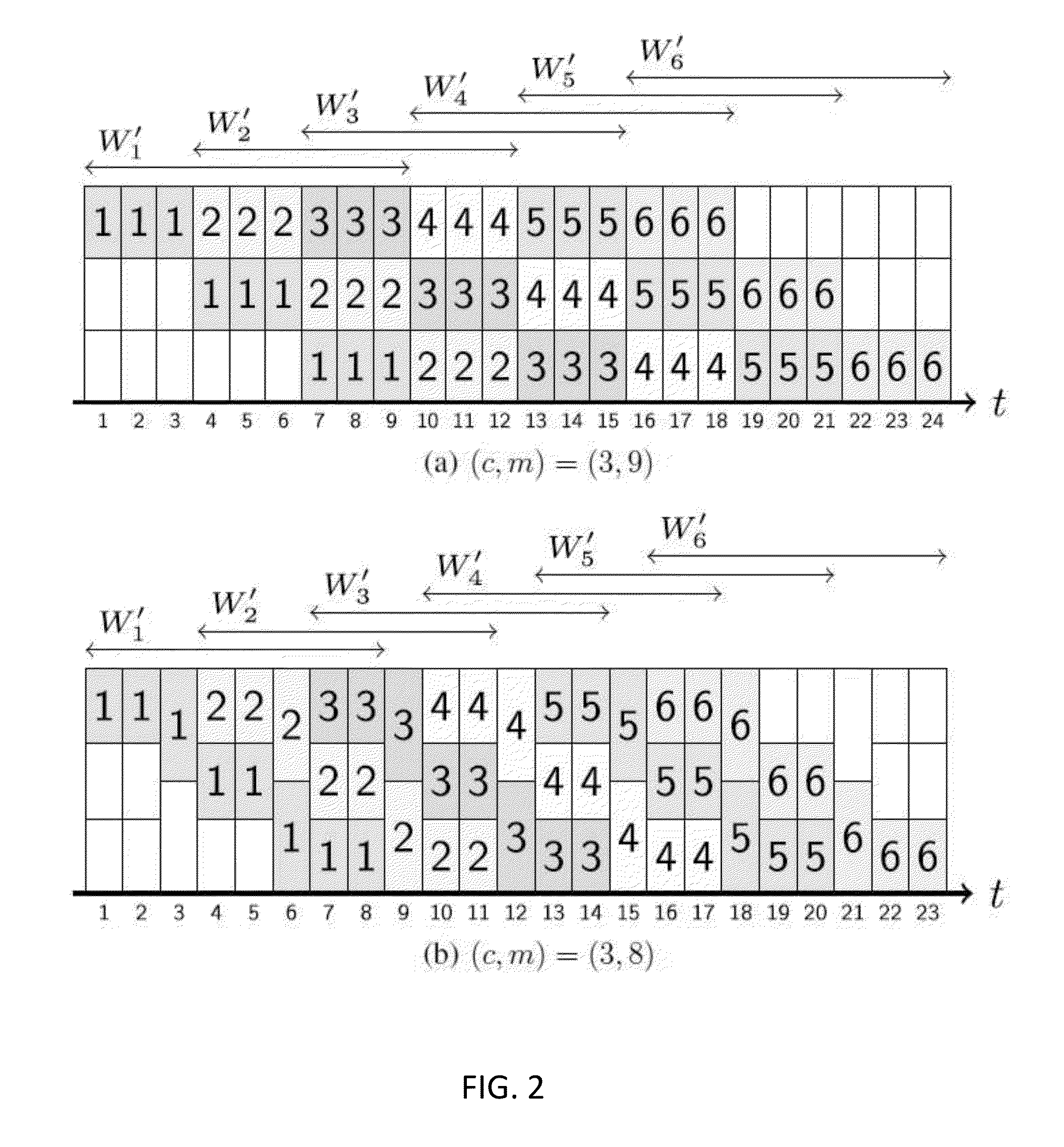
[0055]In the case of the symmetric code, the number of active messages at each time step (e.g. t∈+), for a given choice of (c, m), can be explicitly provided, as demonstrated in Annex A1 which makes part of the present disclosure. As described in Annex A1, there are two distinct cases which dictate differing number of active messages for a time step, as defined by the offset quotient and the offset remainder (as previously defined) of integer parameter sets (t, c) and (m, c):[0056]Case a1: If rt,c≦rm,c, then there are qm,c+1 active messages at time step t, each of which is allocated a block of size 1 / (qm,c+1).[0057]Case a2: If rt,c>rm,c, then there are qm,c active messages at time step t, each of which is allocated a block of size 1 / qm,c.[0058]As noted in Annex A1, which makes part of the present disclosure, when m is a multiple of c, then for any time step t, rt,c≦rm,c=c, which implies that there are qm,c+1 active messages at every time step, and therefore all blocks are of size 1 / ...

case b2

where i∈{1, . . . , m}, one can observe that the size of the block that encodes message k at time step (k−1)c+i, which has been defined as xi, depends on the value of ri,c. As demonstrated in Annex A1, which makes part of the present disclosure, two cases are possible:[0060]Case b1: If ri,c≦rm,c, then xi=1 / (qm,c+1). Since i∈{1, . . . , m}, this condition corresponds to the case where qi,c ∈{0, . . . , qm,c} and ri,c∈{1, . . . , rm,c}. Therefore, message k is allocated a small block size 1 / (qm,c+1) per time step for a total of (qm,c+1)rm,c time steps in the effective coding window W′k.[0061]Case b2: If ri,c>rm,c, then xi=1 / qm,c. Since i∈{1, . . . , m}, this condition corresponds to the case where qi,c∈{0, . . . , qm,c−1} and ri,c∈{rm,c+1, . . . , c}. Therefore, message k is allocated a big block size 1 / qm,c per time step for a total of qm,c(c−rm,c) time steps in the effective coding window W′k.

[0062]Other characteristics of the proposed novel family of symmetric time-invariant intra-...


PUM


Abstract

A computer-based real-time streaming system under packet erasures wherein created messages can be decoded within a fixed delay form their creation is presented. Various code construction methods and corresponding hardware implementation for different cases of erasure link models are also presented.

Description

CROSS REFERENCE TO RELATED APPLICATIONS[0001]The present application claims priority to U.S. provisional Patent Application Ser. No. 61 / 726,131, filed on Nov. 14, 2012, for “Coding Scheme for Real-Time Streaming Communications”, which is herein incorporated by reference in its entirety.STATEMENT OF GOVERNMENT GRANT[0002]This invention was made with government support under FA9550-10-1-0166 awarded by the Air Force. The government has certain rights in the invention.[0003]Throughout the present disclosure reference will be made to the enclosed Annex A1 and Annex A2, both of which make part of the present disclosure.BACKGROUND[0004]1. Technical Field[0005]The present disclosure relates to methods and algorithms related to the field of coding for real-time streaming systems which is covered in various areas such as information theory, coding theory and communication theory, with applications in computer science and telecommunication. In particular, the present disclosure presents novel...

Claims


Application Information

Patent Timeline
Patent Type & Authority Applications(United States)
IPC IPC(8): H04L29/06
CPCH04L65/607H03M13/373H03M13/3761H04N19/89H04N19/67H03M13/1515H03M13/2721H03M13/356H04L65/70H03M13/23H03M13/2909H03M13/2921H03M13/293H03M13/2924H03M13/3723
Inventor LEONG, DEREKQURESHI, ASMAWEI, YUNKAIHO, TRACEY C
Owner CALIFORNIA INST OF TECH
Why Eureka
Try Eureka