Easy Drill Slip with Degradable Materials

Active Publication Date: 2014-08-14
BAKER HUGHES OILFIELD OPERATIONS LLC
View PDF2 Cites 20 Cited by
  • Summary
  • Abstract
  • Description
  • Claims
  • Application Information

AI Technical Summary

Benefits of technology

This patent describes a way to make a slip ring for use in a downhole tool. The slip inserts are cast in a surrounding molding made of a material called phenolic, which provides a protective layer for the slip elements. This helps to prevent the soluble material from dissolving prematurely. The technical effect of this method is that it creates a reliable and durable slip ring for use in downhole tools.

Problems solved by technology

When it is desired to remove the tool from the flowbore, a dissolving agent is used to dissolve away the inner body portions of the slip elements, thereby destroying the integrity of the gripping system of the tool.

Method used


Image

  • Easy Drill Slip with Degradable Materials
  • Easy Drill Slip with Degradable Materials
  • Easy Drill Slip with Degradable Materials

Examples


Embodiment Construction

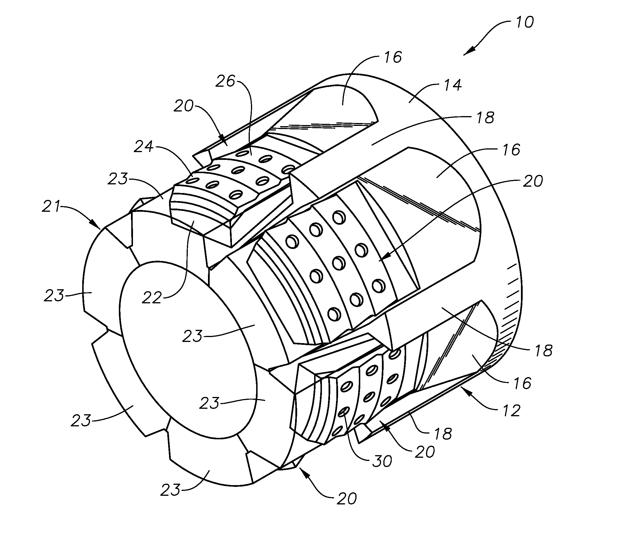
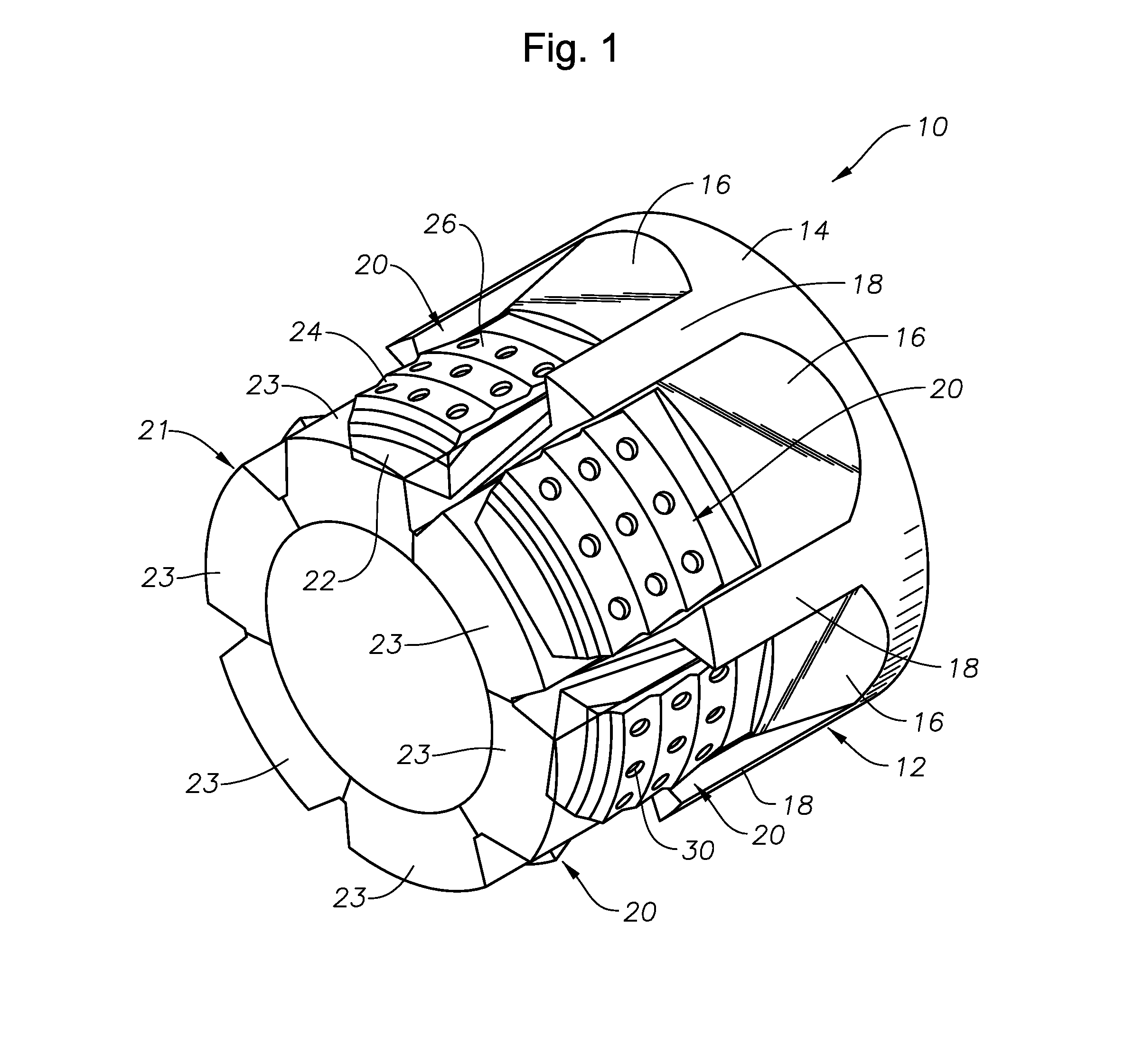
[0023]FIG. 1 depicts an exemplary downhole tool 10 constructed in accordance with the present invention. The tool 10 can be any of a class of devices that use radially moveable slip elements within a gripping system that resists axial or torsional forces. The downhole tools may include packers, anchors, plugs, setting tools, bridge plugs, locks and fishing tools. The downhole tool 10 includes a setting cone 12 which is generally cylindrical. The outer radial surface 14 of the setting cone 12 includes a plurality of angled ramps 16 which are separated by guides 18. A slip element 20, constructed in accordance with the present invention, is located upon each of the ramps 16.

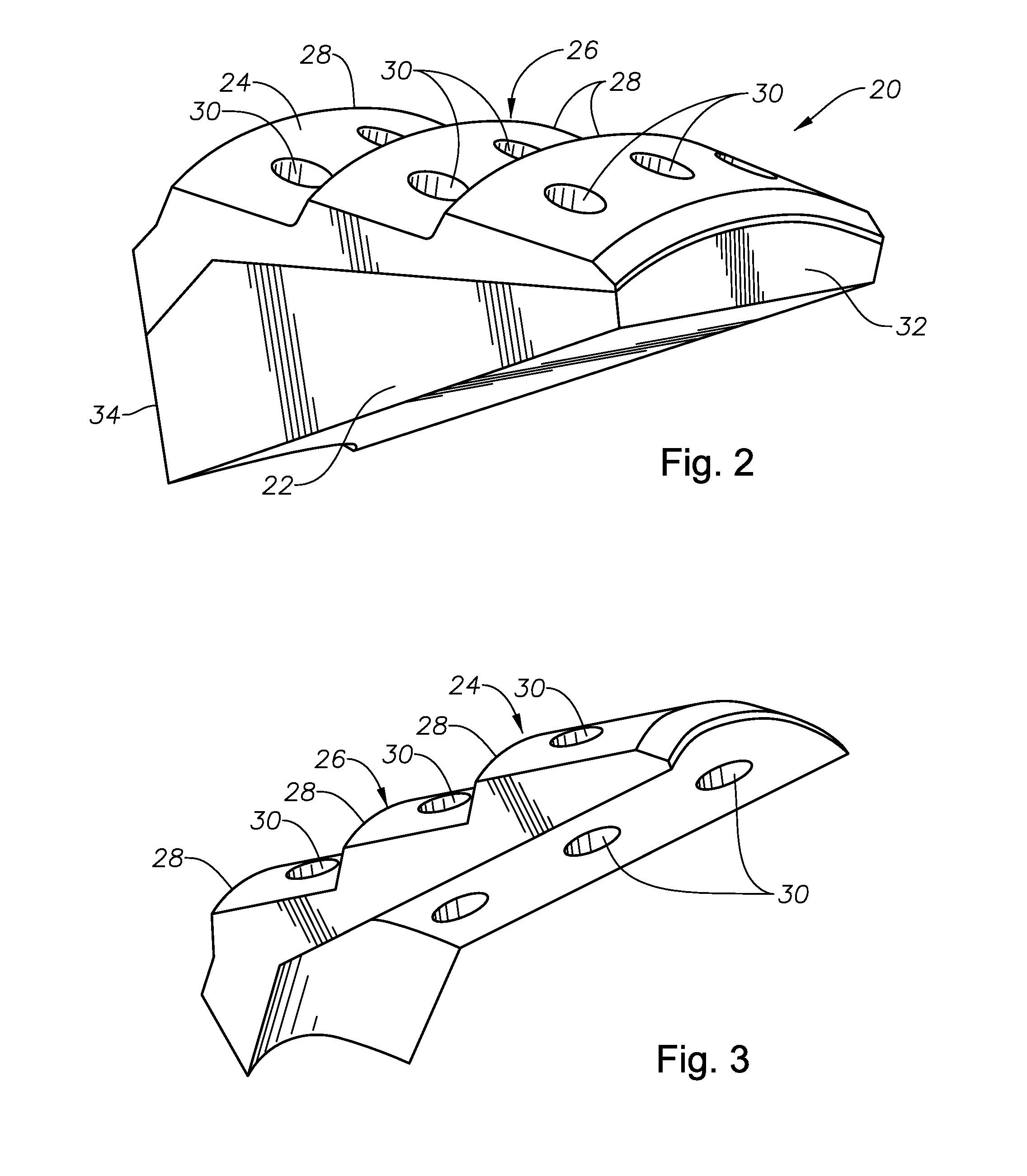
[0024]In preferred embodiments, the slip elements 20 are cast within a surrounding molding 21, which is best seen in FIG. 6. In particular embodiments, the molding 21 is formed of a phenolic resin and is cast in an annular ring shape having sheaths 23. The sheaths 23 each encase one of the slip elements 20. The mol...


PUM


Abstract

Slip elements for a downhole tool include an inner body portion that is substantially formed of a material that is degradable by dissolution in response to a dissolving fluid and a hardened, resilient, radially outer contact portion. The inner body portion may be formed of magnesium, aluminum or iron based powder.

Description

BACKGROUND OF THE INVENTION[0001]1. Field of the Invention[0002]The invention relates generally to the design of slip elements that are used in gripping systems for downhole tools.[0003]2. Description of the Related Art[0004]Numerous downhole tools incorporate gripping systems that use one or more slips. The slips are moved radially outwardly against a surrounding tubular member in order to resist axial or torsional forces, or both. In many instances, slips are set to securely anchor a downhole tool in place within a surrounding tubular member. In other cases, such as with drag blocks, a slip may be set to merely resist axial or torsional movement. Downhole tools that incorporate gripping systems that use slips include, but are not limited to, packers, anchors, plugs, setting tools, bridge plugs, locks and fishing tools. Plugs, for example, have a plug body with slip elements that can be selectively moved radially outwardly to bitingly engage a surrounding tubular member. One type o...

Claims


Application Information

Patent Timeline
IPC IPC(8): E21B23/01
CPCE21B23/01E21B33/129E21B33/134
Inventor XU, RICHARD YINGQINGXU, ZHIYUE
Owner BAKER HUGHES OILFIELD OPERATIONS LLC
Why Eureka
Try Eureka