Novel built-in cable-truss anchoring structure and construction method thereof

A built-in, new type of technology, applied in bridge form, bridge parts, erection/assembly of bridges, etc., can solve problems such as inconvenient construction, damage to the integrity of the bridge deck, and increase the amount of steel used for the main truss joints

Active Publication Date: 2011-11-30
ZHONGTIE MAJOR BRIDGE RECONNAISSANCE & DESIGN INST
View PDF0 Cites 0 Cited by
  • Summary
  • Abstract
  • Description
  • Claims
  • Application Information

AI Technical Summary

Problems solved by technology

There are two traditional structural forms of setting the anchor box at the end of the cable-stayed cable beam outside the node of the main truss: one is to lead the anchor plate above the upper chord node of the main truss to set the anchor box. For the bridge deck, it divides the bridge deck and destroys the integrity of the bridge deck; the other is to set the anchor box under the upper chord node of the main truss.
Moreover, these two structural forms will increase the amount of steel used for the main truss joints

Method used


Image

  • Novel built-in cable-truss anchoring structure and construction method thereof
  • Novel built-in cable-truss anchoring structure and construction method thereof
  • Novel built-in cable-truss anchoring structure and construction method thereof

Examples


Embodiment Construction

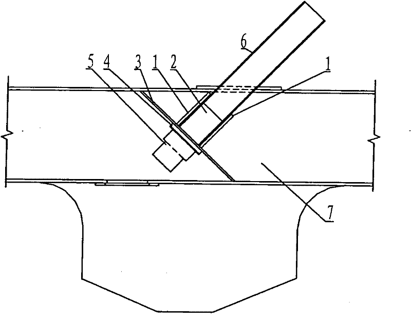
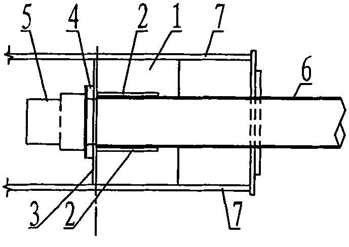
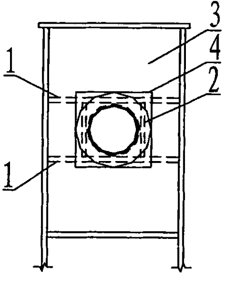
[0018] refer to figure 1 , 2 , 3, 4, 5, the anchor box horizontal bearing plate 1 of the new built-in cable truss anchorage structure of the present invention is welded into an anchor box with the overall gusset plate 7 in the width direction and the vertical bearing plate 2 of the anchor box in the vertical direction, satisfying Stress requirements for panel structures. The lower ends of the vertical load-bearing plate 2 and the horizontal load-bearing plate 1 of the anchor box are welded to the main truss node diaphragm 3, and the main truss node diaphragm 3 is arranged along the vertical direction of the cable axis and placed in the center of the main truss node. 6 is arranged in the anchor box along the cable axis, the lower end is welded together with the main truss node diaphragm, and the anchor backing plate 4 is welded with the lower side of the main truss node diaphragm 3 . The anchor backing plate is divided into two pieces, and the contact surface between the two ...


PUM


Abstract

The invention relates to a novel built-in cable-truss anchoring structure and a construction method thereof. Two anchor box horizontal bearing plates, overall node plates and an anchor box vertical bearing plate are welded to form an anchor box; the lower end of the anchor box vertical bearing plate is welded with a main truss node clapboard; the main truss node clapboard is arranged on the central edge of a main truss node and vertical to the axial direction of a cable; a stay cable conduit is arranged in the anchor box along the axis of a stay cable, and the lower end of the stay cable conduit is welded with the main truss node clapboard; an anchor backing plate is welded with the lower side surface of the main truss node clapboard; and an anchor device is arranged on the lower side of the anchor backing plate. The construction method comprises the following steps: welding two horizontal bearing plates arranged along the axis of the cable on the inner sides of two node plates; welding the anchor box horizontal bearing plates with the overall node plates and the anchor box vertical bearing plate to obtain the anchor box, wherein the lower ends of the horizontal bearing plates andthe vertical bearing plate are vertical to the axis of the stay cable and welded with the main truss node clapboard; welding the anchor backing plate on the lower side of the main truss node clapboard; arranging the cable conduit in the anchor box; and arranging the anchor device of the stay cable on the lower side of the anchor backing plate. The invention has the advantages of small steel dosage and convenient construction without damaging the integrity of bridge floor.

Description

technical field [0001] The patent of the present invention relates to a new type built-in cable truss anchorage structure and its construction method for the anchorage of cable-stayed beam ends. Background technique [0002] In the design of steel truss girder cable-stayed bridges, especially in the design process of long-span and heavy-duty steel truss girder cable-stayed bridges, the pull force of the cable-stayed cables is relatively large. The anchor point of the traditional cable-stayed cable is set outside the main truss node, or the anchor plate is added, and the anchor box is set above the main truss node, or the anchor box is set below the main truss node. The amount of steel used for truss joints. There are two traditional structural forms of setting the anchor box at the end of the cable-stayed cable beam outside the node of the main truss: one is to lead the anchor plate above the upper chord node of the main truss to set the anchor box, and its disadvantage is ...

Claims


Application Information

Patent Timeline
Patent Type & Authority Patents(China)
IPC IPC(8): E01D19/14E01D19/16E01D21/00E01D11/04
Inventor 徐伟肖海珠郭子俊孙英杰高宗余张晓勇鲍莉霞徐科英胡辉跃郑清刚付岚岚梅大鹏
Owner ZHONGTIE MAJOR BRIDGE RECONNAISSANCE & DESIGN INST
Why Eureka
Try Eureka