Button mechanism and related electronic device

a technology of electronic devices and buttons, applied in contact mechanisms, emergency actuators, electrical devices, etc., can solve the problems that the button mechanism b>10/b> cannot provide touching feel, and achieve the effect of increasing the structural strength and stability of the button (combined with the supporting portion and the pressing portion), simple structure, and easy operation

Active Publication Date: 2014-08-14
WISTRON CORP
View PDF4 Cites 2 Cited by
  • Summary
  • Abstract
  • Description
  • Claims
  • Application Information

AI Technical Summary

Benefits of technology

[0006]The present invention provides a button mechanism and a related electronic device with strong structure and stably touching feel for solving above drawbacks.
[0018]The button mechanism of the present invention has advantages of simple structure and easy operation. The drawing die is not generated when manufacturing the erect supporting portion, so that structural strength and stability of the button (combined with the supporting portion and the pressing portion) can be increased. The button mechanism of the present invention disposes the erect supporting portion on two ends of the stretching line of the gravity of the pressing portion, and replaces the conventional arm by the resilient component for providing the uniformly resilient recovering force, so as to enhance the touching feel and product yield of the button mechanism for increasing market competition.

Problems solved by technology

However, the resilient arm 16 is the Z-shaped structure, which forms structural defect easily due to difficult manufacturing, and the resilient arm 16 is easy to be resiliently deformed unexpectedly.
In addition, the button mechanism 10 has small structural configuring space, the resilient arm 16 is often designed as thin-typed structure, which is easily broken or losses resilient recovering force after long-period operation, and the button mechanism 10 can not provide touching feel.
Thus, design of a button mechanism having strong structure and stably touching feel is an important issue in the computer mechanical design industry.

Method used


Image

  • Button mechanism and related electronic device
  • Button mechanism and related electronic device
  • Button mechanism and related electronic device

Examples


Embodiment Construction

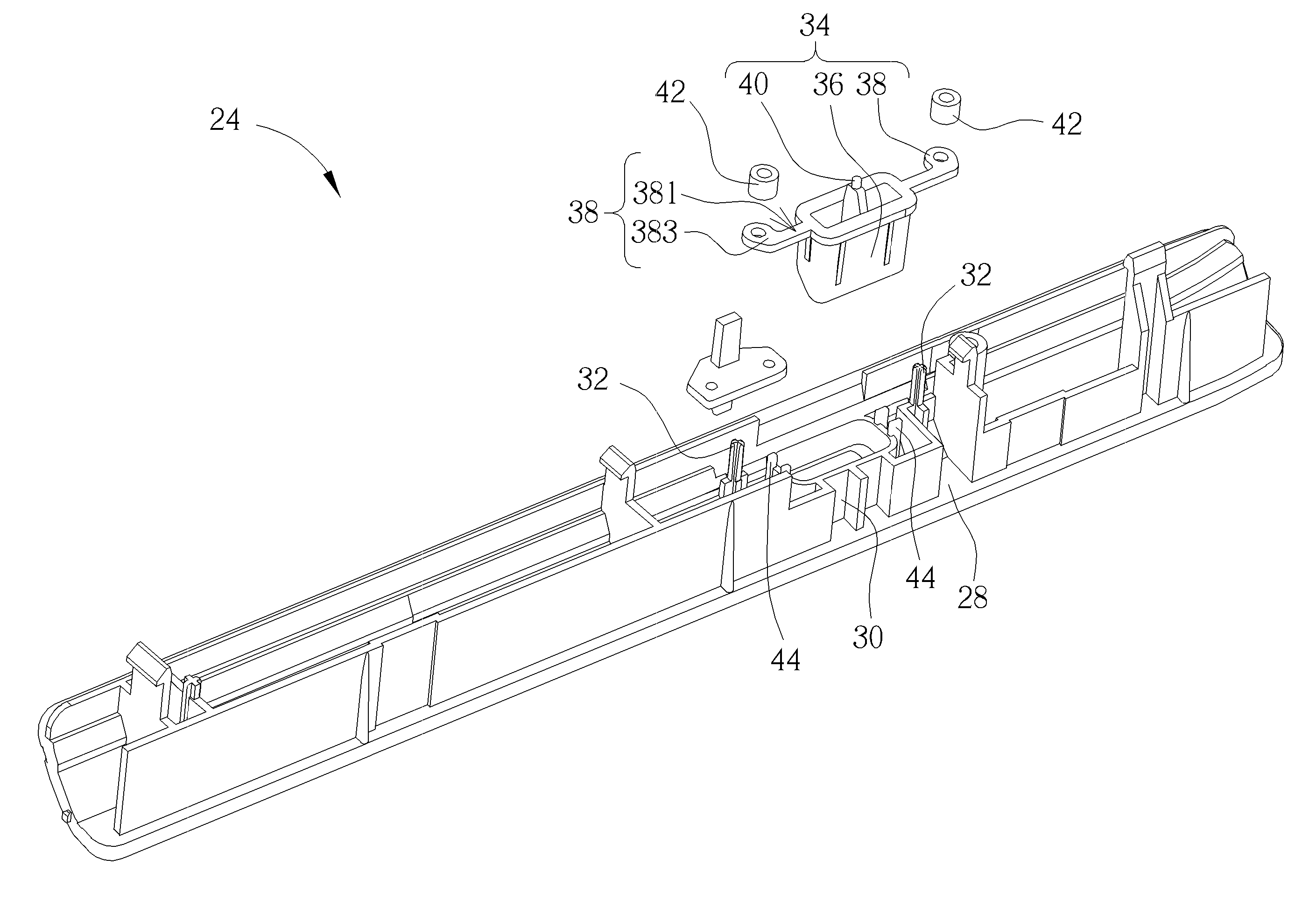
[0027]Please refer to FIG. 3. FIG. 3 is a diagram of an electronic device 20 according to an embodiment of the present invention. The electronic device 20 includes an optical disk drive 22 and a button mechanism 24. The button mechanism 24 is disposed by the optical disk drive 22, and the user can press the button mechanism 24 to actuate a switch 26 of the optical disk drive 22. The button mechanism 24 of the present invention not only can prevent the pressing function from inefficacy due to permanent deformation of the resilient component as the prior art, but also provide stable guiding function, so that a button of the button mechanism 24 is not shifted when moving, and the button mechanism 24 can have preferred touching feel.

[0028]Please refer to FIG. 4 and FIG. 5. FIG. 4 is an exploded diagram of the button mechanism 24 according to the embodiment of the present invention. FIG. 5 is an assembly diagram of the button mechanism 24 according to the embodiment of the present invent...


PUM


Abstract

A button mechanism includes a base, a button and two resilient components. The base includes an accommodating slot structure and two guiding pillars, the pillars are disposed by sides of the accommodating slot structure. The button includes a pressing portion and two supporting portions. The pressing portion is movably disposed inside the accommodating slot structure. The supporting portions are respectively disposed by opposite sides of the pressing portion. A first end of the supporting portion is connected to the pressing portion, and a second end of the supporting portion is slidably disposed on the guiding pillar. Two ends of the resilient component respectively contact against an optical disk driver and the supporting portion. The supporting portion slides relative to the guiding pillar to compress the resilient component, and a resilient recovering force of the resilient component drives the supporting portion to slide relative to the guiding pillar inversely.

Description

BACKGROUND OF THE INVENTION[0001]1. Field of the Invention[0002]The present invention relates to a button mechanism and a related electronic device, and more particularly, to a button mechanism and a related electronic device with strong structure and stably touching feel.[0003]2. Description of the Prior Art[0004]Please refer to FIG. 1 and FIG. 2. FIG. 1 is an exploded diagram of a button mechanism 10 in prior art. FIG. 2 is an assembly diagram of the button mechanism 10 in prior art. The button mechanism 10 includes a base 12, a body 14 and two resilient arms 16. The body 14 is movably disposed inside a sunken slot 121 on the base 12. The base 12 further includes two guiding bars 123 respectively disposed by sides of the sunken slot 121. Ends of the resilient arms 16 are disposed on a side of the body 14 not adjacent to the guiding bar 123, and the other end of each resilient arm 16 is fixed on the corresponding guiding bar 123. As shown in FIG. 1, the resilient arm 16 is a curved...

Claims


Application Information

Patent Timeline
Patent Type & Authority Applications(United States)
IPC IPC(8): H01H3/12
CPCH01H3/12H01H13/52H01H2221/036
Inventor WANG, YUN-JUN
Owner WISTRON CORP
Why Eureka
Try Eureka