Light emitting device
a technology of light-emitting devices and light-emitting components, which is applied in the direction of semi-conductor devices, basic electric elements, electrical apparatus, etc., can solve the problems of self-alignment problems in relation to csp, and achieve the effect of effectively preventing self-alignment problems
- Summary
- Abstract
- Description
- Claims
- Application Information
AI Technical Summary
Benefits of technology
Problems solved by technology
Method used
Image
Examples
first embodiment
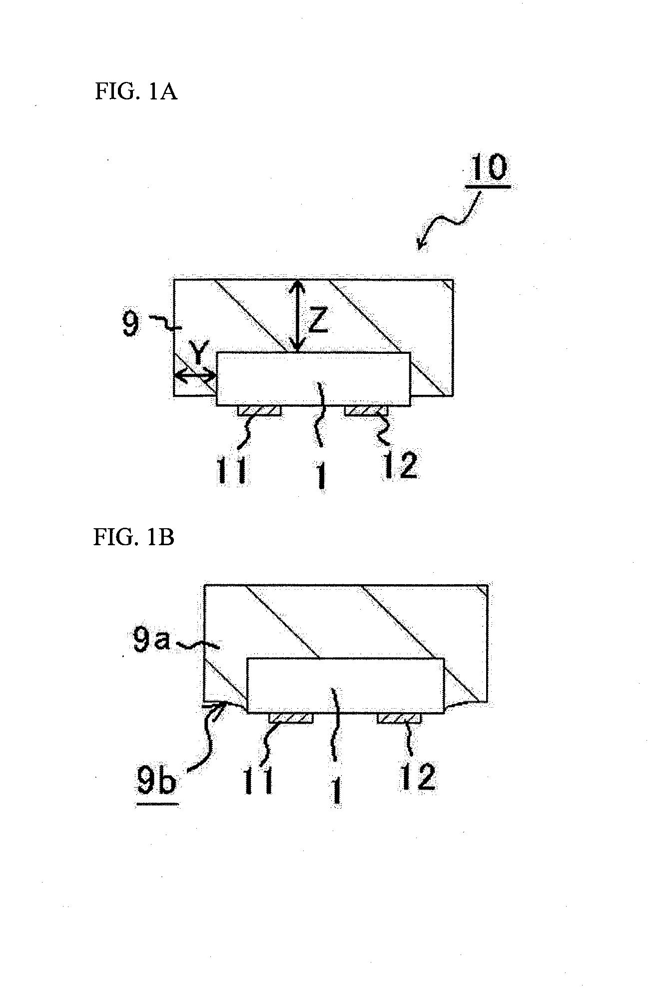
[0035]As illustrated in FIG. 1A, the light emitting device 10 according to this embodiment includes a light emitting element 1, a first outer connection electrode 11 and a second outer connection electrode 12 that are respectively connected to a first electrode and a second electrode of the light emitting element 1 as described below, and a resin layer 9 that is configured to cover the lower surface and side surface of the light emitting element 1. The upper surface of the resin layer 9 is disposed at a position that is lower than the upper surface of a semiconductor laminated body.
[0036]The light emitting device normally has a planar configuration in the shape of a rectangle or substantially in the shape of a rectangle. As used herein, “substantially in the shape of a rectangle” means that a fluctuation is allowed in the angle of the four corners of 90±10 degrees.
[Light Emitting Element]
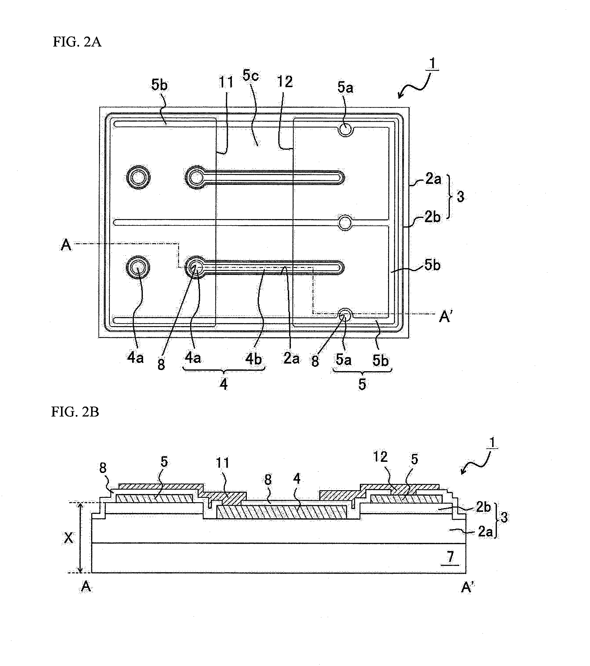
[0037]As illustrated in FIG. 2A and FIG. 2B, the light emitting element 1 has a semiconductor la...
second embodiment
[0072]As illustrated in FIG. 4A, the light emitting device 20 according to this embodiment includes a second resin layer 18 that contains a fluorescent material on the lower surface of the of the light emitting element 1 in addition to the resin layer 19 on the side surface of the light emitting element 1, and in other respects has the substantially the same configuration as the light emitting device 10 according to the first embodiment.
[0073]The resin layer 19 may expose a portion of the side surface of the semiconductor laminated body 3 (reference is made to FIG. 4A), or although the side surface of the semiconductor laminated body 3 is covered, the upper surface 19b of the resin layer 19a may become gradually lower in accordance with separation from the semiconductor laminated body 3 (reference is made to FIG. 4B).
[0074]The resin layer 19 and the second resin layer 18 may be formed by the following method.
[0075]As illustrated in FIG. 5A, the light emitting element 1 is adhere to ...
third embodiment
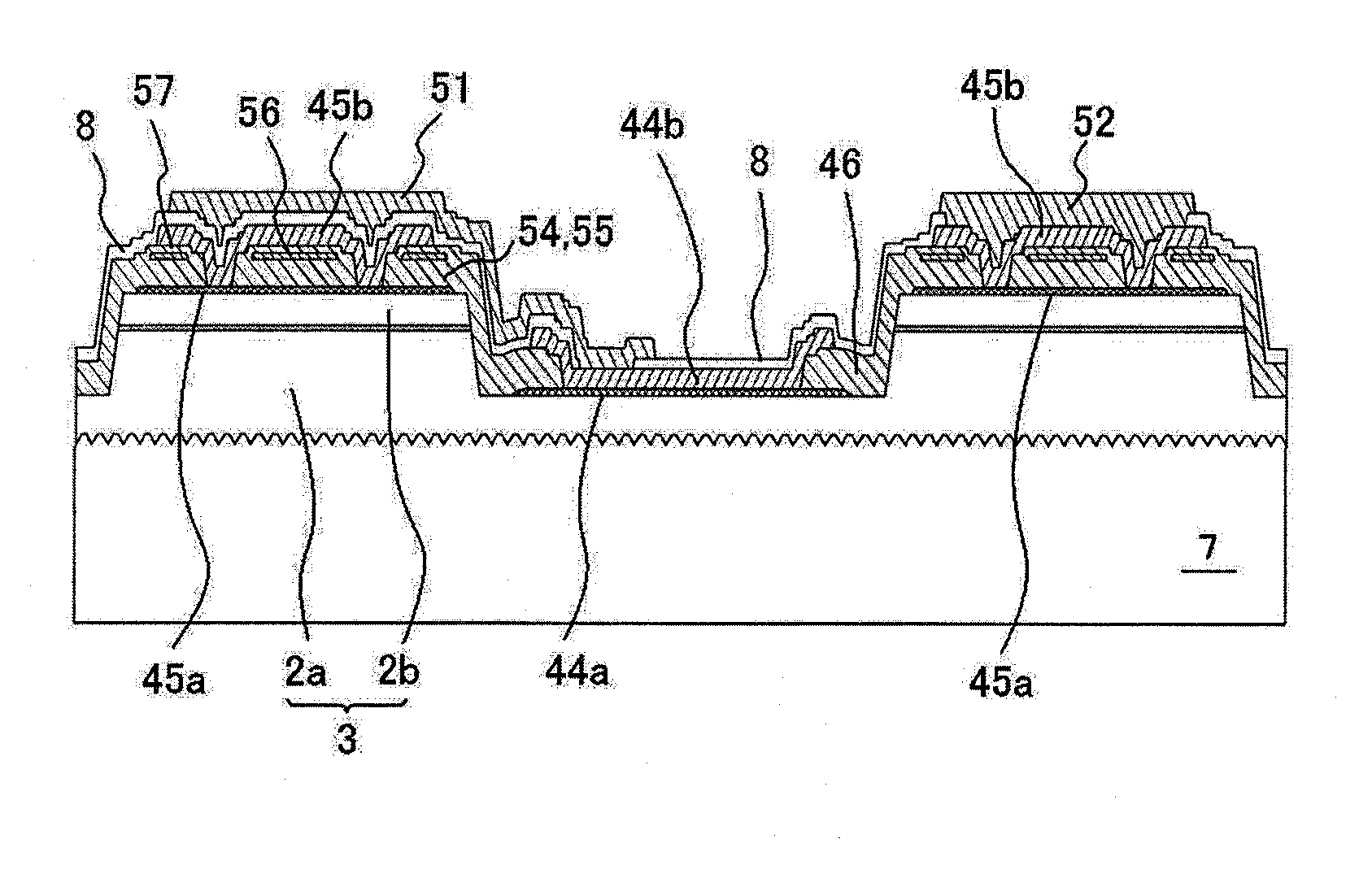
[0080]As illustrated in FIG. 6A and FIG. 6B, the light emitting device according to the present embodiment has a different structure in relation to the first electrode 34 and the second electrode 35 of the light emitting element as described below, and in other respects has the substantially the same configuration as the light emitting device 10 according to the first embodiment.
[0081]An insulating film 38 may be disposed between the first outer electrode 11 and the second outer electrode 12 on the lower surface of the light emitting device. The disposition of the insulating film 38 enables prevention of an electrical connection between those two electrodes. Furthermore, a short circuit connection can be prevented in relation to both outer electrodes of the joint material during mounting operations.
(First Electrode and Second Electrode)
[0082]The first electrode 34 and the second electrode 35 of the light emitting device 31 includes a first ohmic electrode 34a and a second ohmic elec...
PUM
 Abstract
Description
Claims
Application Information
 - R&D
- Intellectual Property
- Life Sciences
- Materials
- Tech Scout
- Unparalleled Data Quality
- Higher Quality Content
- 60% Fewer Hallucinations
Browse by: Latest US Patents, China's latest patents, Technical Efficacy Thesaurus, Application Domain, Technology Topic, Popular Technical Reports.
© 2025 PatSnap. All rights reserved.Legal|Privacy policy|Modern Slavery Act Transparency Statement|Sitemap|About US| Contact US: help@patsnap.com


