Process and system to determine temporal changes in retransmission and propagation of signals used to measure distances, syncronize actuators and georeference applications

Active Publication Date: 2014-08-14
INST PRESBITERIANO MACKENZIE
View PDF12 Cites 7 Cited by
  • Summary
  • Abstract
  • Description
  • Claims
  • Application Information

AI Technical Summary

Benefits of technology

The present invention allows for the accurate positioning and adjustment of time for a repeater station that is far from a known site and has a transponder. This is done by analyzing the time changes in retransmission and propagation of signals received from a stationary transmitter.

Problems solved by technology

Factor (d), however, is undetermined, since the remote object is inaccessible for direct measurements and it undergoes to changes in its internal signal propagation characteristics, which can change with time, or for each sequence of signals utilized to determine its distance.
On the other hand, when using meteor as reflecting transponders, phase delays can be caused by the signal scattering on the ionized trails (Wislez J.-M., “Forward Scattering of Radio Waves of Meteor Trails”, Proceedings of the International Meteor Conference, Brandenburg, Alemanha, pp.
This option, however might not be always practical, being certainly expensive.
However the continuous use and the remote and inaccessible location of a defined link as, for example, in a satellite, jeopardizes the maintenance of the delays previously determined and makes impossible its updating correction.
The difficulties become aggravated when adding imponderable signal phase changing physical effects—such as effect due to temperature variations in the electronic circuits at the repeater.

Method used


Image

  • Process and system to determine temporal changes in retransmission and propagation of signals used to measure distances, syncronize actuators and georeference applications
  • Process and system to determine temporal changes in retransmission and propagation of signals used to measure distances, syncronize actuators and georeference applications
  • Process and system to determine temporal changes in retransmission and propagation of signals used to measure distances, syncronize actuators and georeference applications

Examples


Embodiment Construction

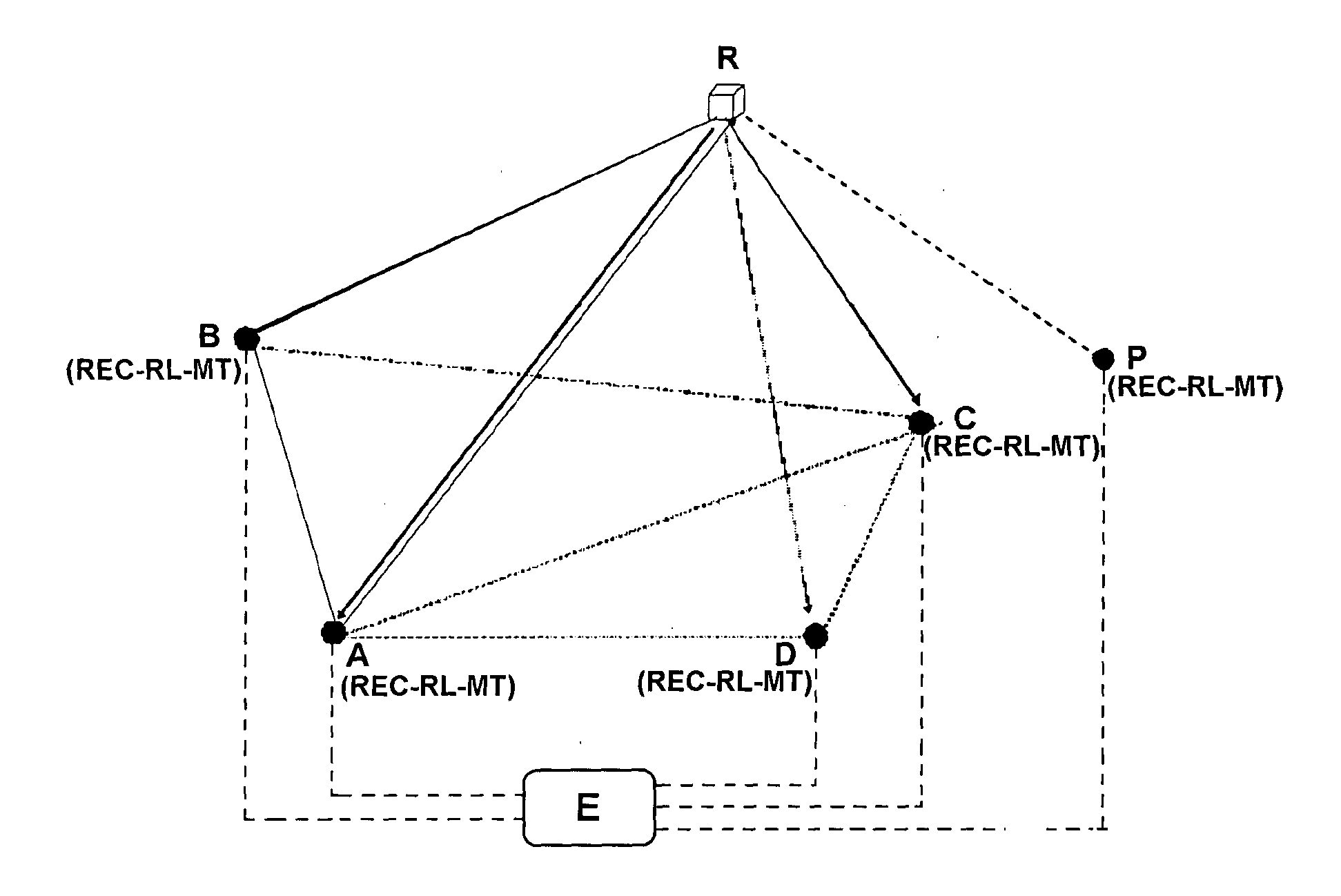
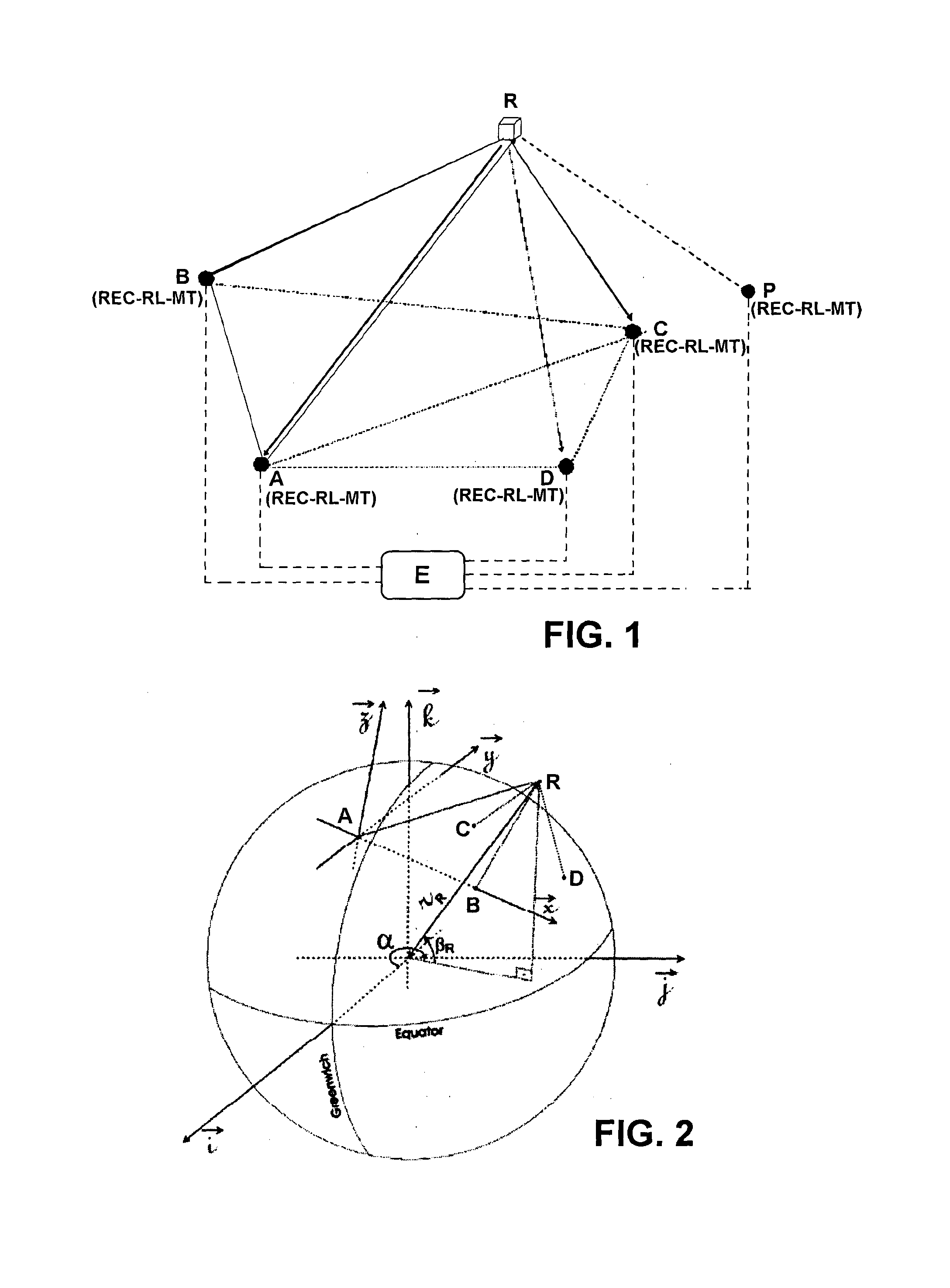
[0029]As mentioned before, and illustrated in the attached FIG. 1, the invention provide a process and a system for wireless transmission of signals, as for example digital audio or video signals, or even analog signals, with the use of a repeater station R, remote and inaccessible, which may be represented by a satellite platform or of another object or repeater device of any kind, capable to receive and retransmit, in predetermined directions, the coded time signals.

[0030]The invention here presented utilizes four reference bases A, B, C, and D, every three of them not collinear, installed on the ground (see FIG. 1) at known geographic positions with each one of the bases containing signal receiving devices, such as radio frequency signals, modulated digitally, for example, in audio or video, and received and retransmitted by the repeater station R in space. Time coded signals are transmitted by one of the reference bases A, B, C and D and retransmitted by the repeater station R i...


PUM


Abstract

The proposed solution includes the use of four reference bases on the ground at known positions, with a coded time signal transmitted by one of them which is retransmitted by the repeater station and received by each of the reference bases. Using two distinct sets of three reference bases it is possible to calculate the differences between two positions for the repeater station, assigning to the later changes in time, phase or frequency as well as temporal changes due to the signal propagation in the medium, for the respective elevation angles found for the repeater. It can be then identified which values attributed to the temporal changes produces a minimum difference between the two respective positions of the repeater station. The identified temporal change can be used for the correct determination of the repeater station and its use on pertinent applications.

Description

FIELD OF INVENTION[0001]The present invention addresses to a process and a system to determine changes in time, phase and frequency at a signal repeater station located at a remote and inaccessible site, being operatively associated to a set of ground-based transmitting and receiving bases, at known geodetic positions, as well as to determine temporal changes due to the signals propagation in the medium, to obtain distance measurements, navigation and geographic positioning, relative to the inaccessible repeater, and to obtain time synchronization through measurements corrected for the changes in frequency (phase delays) and in time at the remote signal repeater. This proposal provides an innovative solution for the remote determination of time changes and of signal transit times in the process of being received and retransmitted by repeater stations or transponders operating at inaccessible conditions and of the additional time changes caused by the signal propagation in the medium...

Claims


Application Information

Patent Timeline
IPC IPC(8): G01S1/04
CPCG01S1/04G01S5/021G01S13/878G01S5/0263G01S19/31G01S5/06G01S5/04
Inventor KAUFMANN, PIERRELEVIT KAUFMANN, PEDRO
Owner INST PRESBITERIANO MACKENZIE
Why Eureka
Try Eureka