Head mounted display, control method for head mounted display, and image display system

Active Publication Date: 2014-08-14
SEIKO EPSON CORP
View PDF6 Cites 40 Cited by
  • Summary
  • Abstract
  • Description
  • Claims
  • Application Information

AI Technical Summary

Benefits of technology

[0008]An advantage of some aspects of the invention is to solve at least a part of the

Problems solved by technology

However, in the techniques disclosed in the above patent documents, there is a concern that an object cannot be automatically tracked and thus an image ther

Method used


Image

  • Head mounted display, control method for head mounted display, and image display system
  • Head mounted display, control method for head mounted display, and image display system
  • Head mounted display, control method for head mounted display, and image display system

Examples


modification examples

C. Modification Examples

[0121]In addition, the invention is not limited to the above-described embodiments, and can be implemented in various aspects within the scope without departing from the spirit thereof. For example, the following modifications are possible.

modification example 1

C1. Modification Example 1

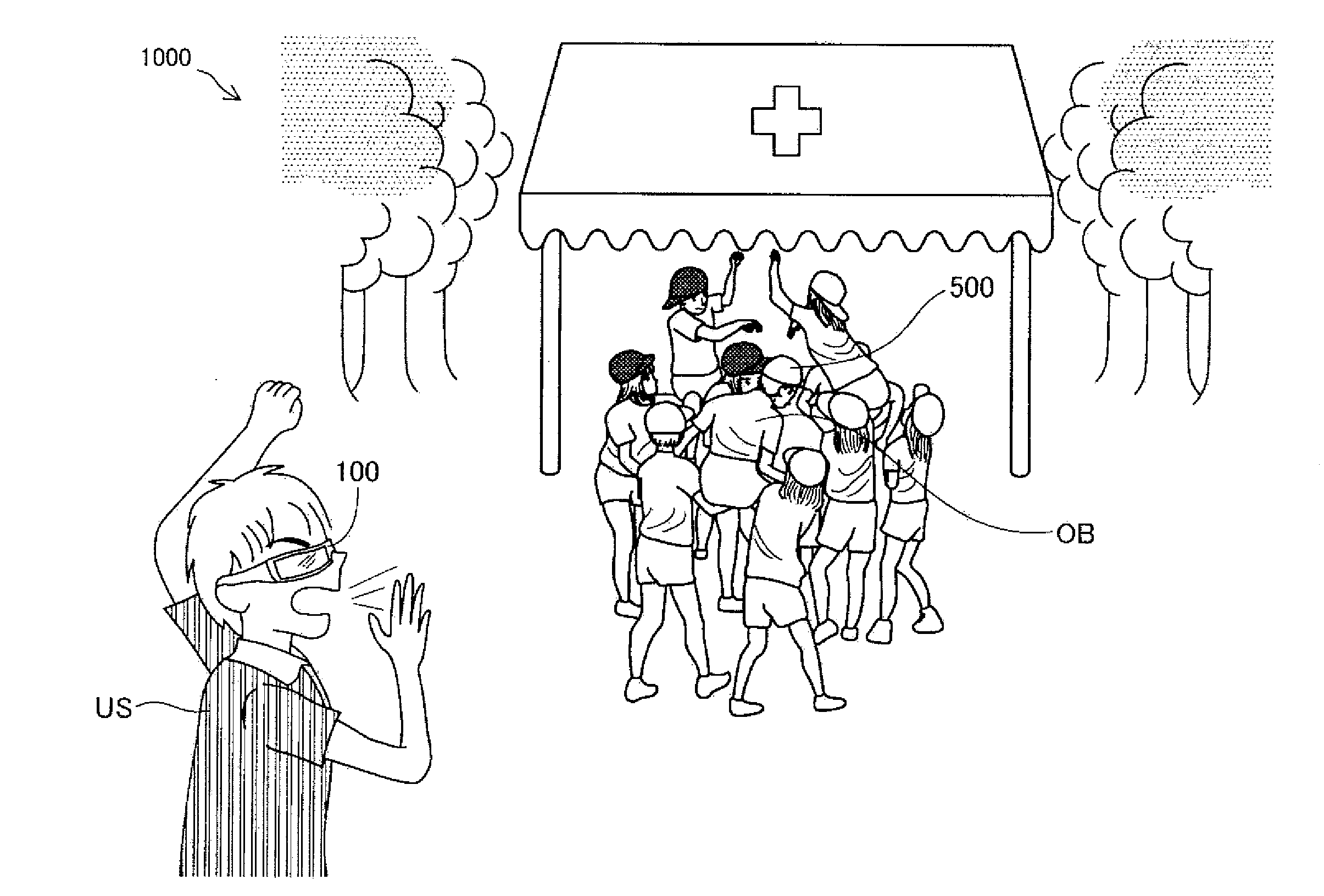
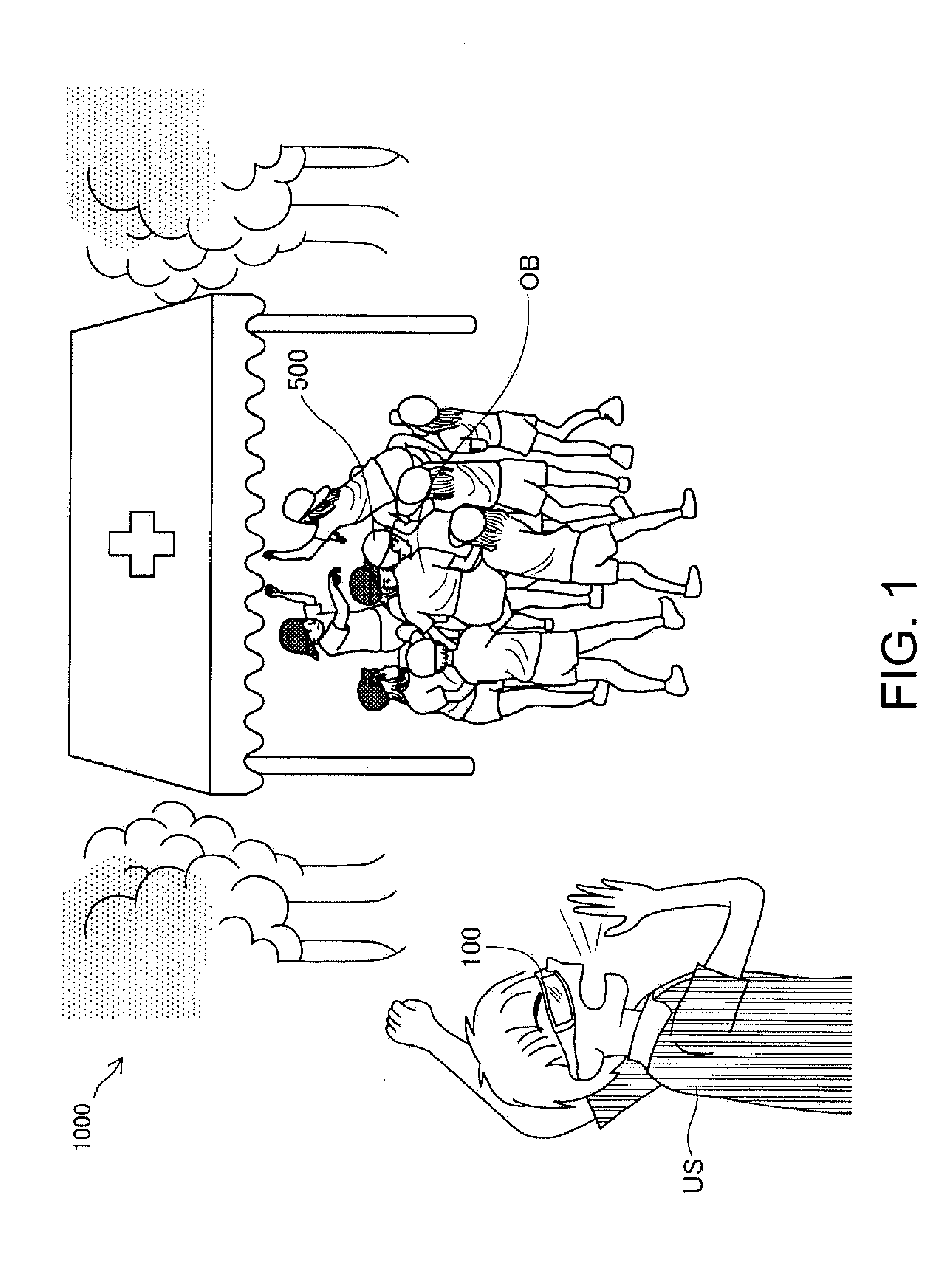
[0122]In the above-described embodiments, as illustrated in FIG. 12, a description has been made of an aspect in which the bird's eye view VI1 and the captured image VI2 are displayed in the lower right region when the maximal image display region PN is divided into nine regions, but the region where the bird's eye view VI1 and the captured image VI2 are displayed may have various modifications. FIG. 13 is a diagram illustrating an example of a visual field VR recognized by the user US. In FIG. 13, unlike in FIG. 12 in the above-described embodiments, a position where the captured image VI2 is displayed in the maximal image display region PN is different. In the head mounted display 100 of Modification Example 1, the control section 10 sets a position where the captured image VI2 is displayed in the maximal image display region EN, to a position which does not overlap with the object OB in the maximal image display region EN on the basis of a specified posi...

modification example 2

C2. Modification Example 2

[0125]In the above-described embodiments, an image indicating a position of the object OB, displayed in the maximal image display region PN, and a position of the image in the maximal image display region PN are changed based on a relative position of the object OB for the user US, but the image and the position where the image is displayed are not limited thereto, and may have various modifications. FIG. 14 is a diagram illustrating an example of a visual field VR recognized by the user US. As illustrated in FIG. 14, an arrow MK4 as an image indicating a position of the object OB is displayed in a part including the center of the maximal image display region PN. In FIG. 14, the object OB is not included in the visual field VR of the user US, and the arrow MK4 indicates that the object OB is present on the right of the user US. In the head mounted display 100 of Modification Example 2, in a case where the object OB is included in the visual field VR of the ...


PUM


Abstract

A transmission type head mounted display includes an image display unit that forms an image on the basis of image data and allows the formed image to be visually recognized by a user as a virtual image in a state in which the image display unit is mounted on the head of the user, a position specifying unit that specifies a target position which is a position of a specific target object relative to the image display unit; and a control unit that causes the image display unit to form a target position display image indicating the target position and that sets a position of the target position display image in an image formation region which is a region where the image display unit forms an image, on the basis of the target position specified by the position specifying unit.

Description

BACKGROUND[0001]1. Technical Field[0002]The present invention relates to a head mounted display.[0003]2. Related Art[0004]A head mounted display (HMD) which is a display mounted on the head is known. The head mounted display generates image light representing an image by using, for example, a liquid crystal display and a light source, and guides the generated image light to user's eyes by using a projection optical system or a light guiding plate, thereby causing the user to visually recognize a virtual image. Of the head mounted display, there are two types including a transmission type in which a user can visually recognize external scenery in addition to a virtual image and a non-transmission type in which the user cannot visually recognize the external scenery. The transmission type head mounted display includes an optical transmission type display and a video transmission type display.[0005]On the other hand, a video camera which is an automatic tracking type image capturing ap...

Claims


Application Information

Patent Timeline
IPC IPC(8): G02B27/01
CPCG02B27/0172G02B27/0093G02B27/017G02B2027/0138G02B2027/014G06F3/013G06F3/04815
Inventor HOSOYA, YOSHINORI
Owner SEIKO EPSON CORP
Why Eureka
Try Eureka