Image processing apparatus, image capturing apparatus, control method, and recording medium
a technology of image processing and image capturing, which is applied in the direction of image enhancement, television systems, instruments, etc., can solve the problems that have not yet been proposed, and achieve the effect of favorable reconstructed images
- Summary
- Abstract
- Description
- Claims
- Application Information
AI Technical Summary
Benefits of technology
Problems solved by technology
Method used
Image

Examples
first embodiment
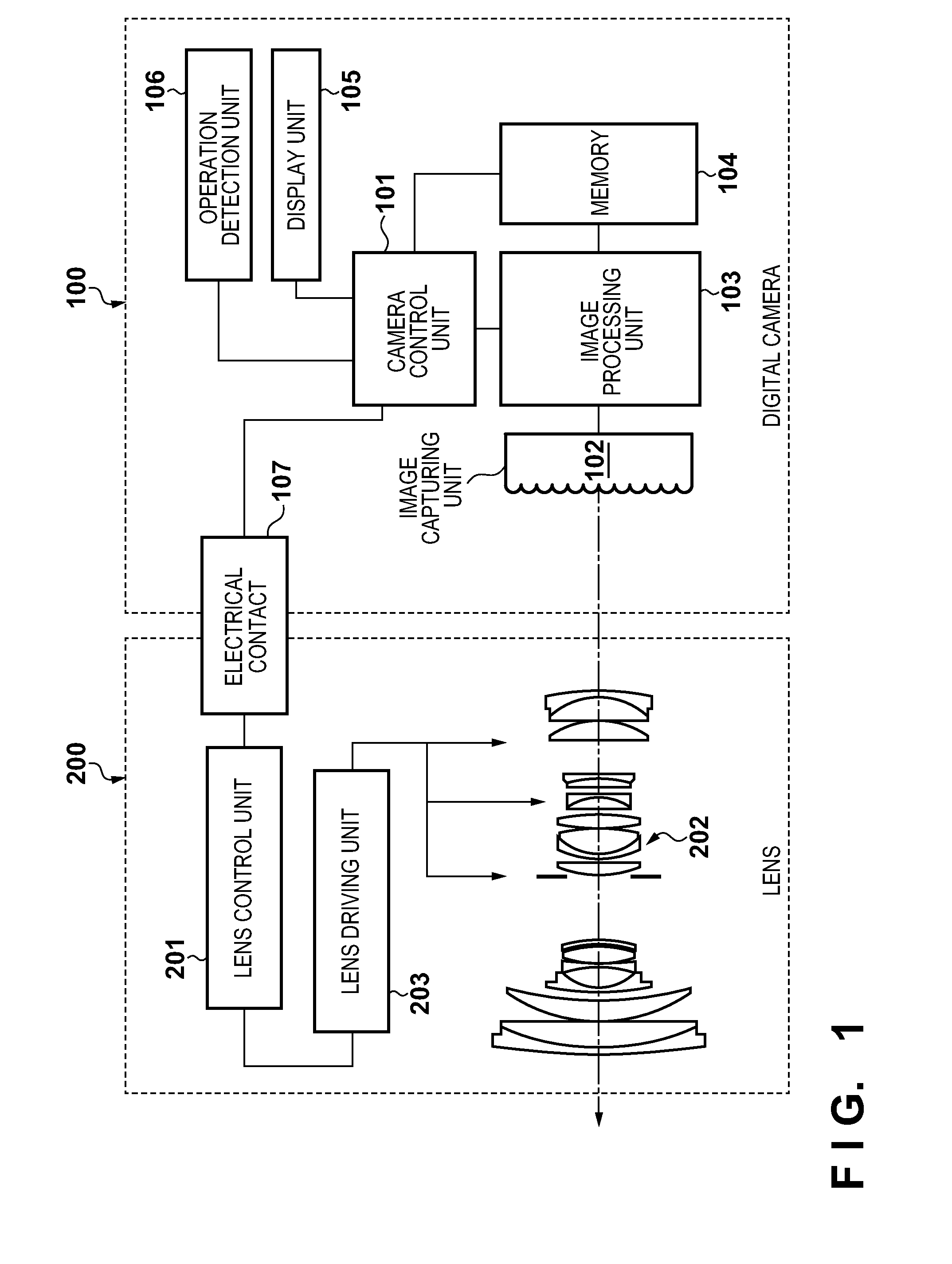
[0026]Hereinafter, exemplary embodiments of the present invention will be described in detail with reference to the drawings. Some of the following embodiments describe examples of applying the present invention in a camera system, which serves as an example of an image processing apparatus, that includes an image capturing apparatus capable of obtaining a plurality of image signals obtained by shooting the same subject at the same time from different positions. However, the present invention can also be applied in any device capable of obtaining a plurality of image signals obtained by shooting the same subject at the same time from different positions.
[0027]Definitions of terms used in this specification will be given below.
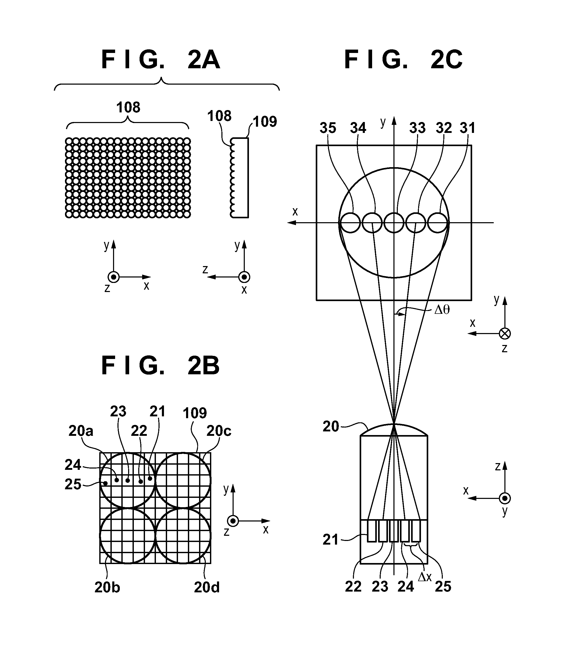
[0028]“LF Data”
[0029]An image signal, output from an image capturing unit 102 provided in a digital camera 100 according to the present embodiment, to which a predetermined image process associated with developing an image has been applied. In the LF data, each...
second embodiment
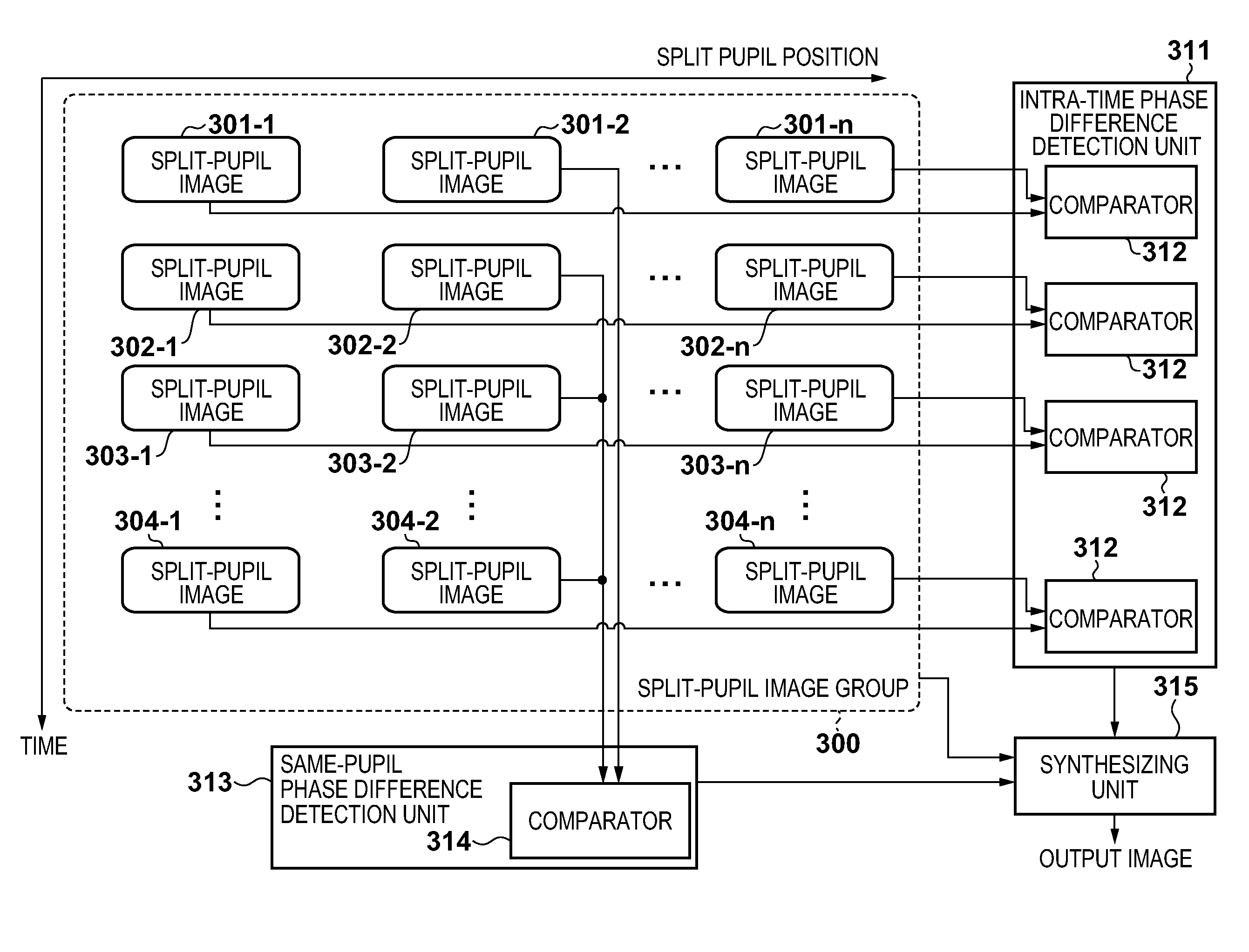
[0092]In the aforementioned first embodiment, the intra-time phase difference detection unit 311 and the same-pupil phase difference detection unit 313 obtain, as the phase difference of the primary subject, a phase difference obtained by performing detections on all regions in the split-pupil images. With the image processing unit 103 according to the present embodiment, however, a subject detection unit 700 that detects a phase difference for a specific subject such as a person's face is provided, as shown in FIG. 7.
[0093]For example, consider a case where a luminance image of interest for the comparators 312 of the intra-time phase difference detection unit 311 and the comparator 314 of the same-pupil phase difference detection unit 313 is taken as a luminance image in a split-pupil image assigned the reference numeral 2. At this time, the luminance image of interest is also input into the subject detection unit 700, and information of a subject position that has been detected is...
third embodiment
[0094]With the image processing unit 103 according to the present embodiment, the synthesizing unit 315 is, as shown in FIG. 8, divided into synthesizers 812 of an intra-time synthesizing unit 811, and a same-pupil synthesizing unit 813.
[0095]In the process of generating the reconstructed image according to the present embodiment, first, the intra-time phase difference detection unit 311 detects a phase difference among split-pupil images generated from LF data shot at the same time. Then, each synthesizer 812 in the intra-time synthesizing unit 811 synthesizes all of the split-pupil images generated from the LF data shot at each time, in accordance with the detected phase difference, and generates a synthesized image focusing on the primary subject for each time (that is, an intra-time synthesized image).
[0096]The comparator 314 of the same-pupil phase difference detection unit 313 detects a phase difference between the generated intra-time synthesized image. The intra-time synthes...
PUM
 Abstract
Description
Claims
Application Information
 - R&D
- Intellectual Property
- Life Sciences
- Materials
- Tech Scout
- Unparalleled Data Quality
- Higher Quality Content
- 60% Fewer Hallucinations
Browse by: Latest US Patents, China's latest patents, Technical Efficacy Thesaurus, Application Domain, Technology Topic, Popular Technical Reports.
© 2025 PatSnap. All rights reserved.Legal|Privacy policy|Modern Slavery Act Transparency Statement|Sitemap|About US| Contact US: help@patsnap.com