Razor blade, razor head, and method of manufacture
Active Publication Date: 2014-08-21
BIC VIOLEX SA
View PDF16 Cites 30 Cited by
Summary
Abstract
Description
Claims
Application Information
AI Technical Summary
This helps you quickly interpret patents by identifying the three key elements:
Problems solved by technology
Method used
Benefits of technology
Benefits of technology
The patent text discusses the issues with handling and assembling blades that are smaller than 1.1 and the increased likelihood of damaging the cutting edge during manufacturing. The text also mentions that controlling the spring force applied by lateral spring arms in heads with movable blades becomes difficult. The patent discusses a solution by applying a mechanical stress after bending a blade to straighten it and reduce the number of products that do not meet geometrical specifications.
Problems solved by technology
Yet, the assembly of these two parts raises the following problems: It is logistically difficult to handle these two different parts; it is difficult to technically handle these very tiny parts in a manufacturing apparatus operating at speeds suitable to reach the demand; it is difficult to guarantee precision of this assembly at these operating speeds, and these assemblies may corrode at the location of the attachment, thereby reducing life expectancy of the overall product.
However, development of such an integral bent blade is very difficult.
However, for integral bent blades, there is a need to provide a product both with excellent formability and cutting performance, while still considering the manufacturing process and cost issues.
However, it is believed that this process still provides a wide dispersion of resulting geometries.
Method used
Image
Click on the blue label to locate the original text in one second.
Reading with bidirectional positioning of images and text.
Examples
first embodiment
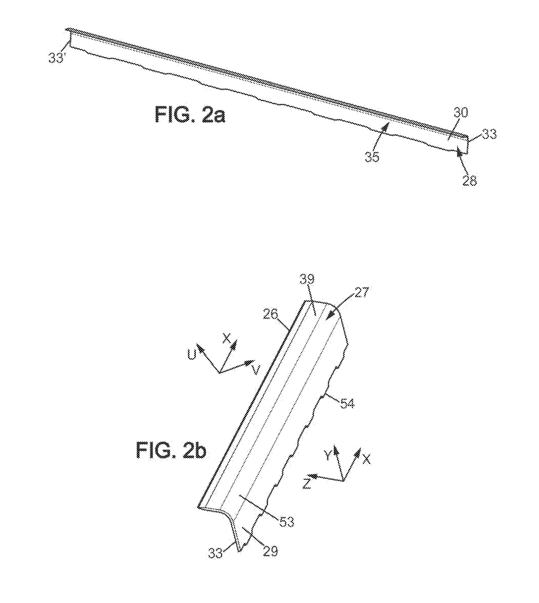
[0144]a bent blade is shown on FIGS. 3a and 3b. Below, some geometrical characteristics of the blade are given. The geometrical characteristics of the blade are here nominal characteristics, which do not take into account the actual geometry of the blade due to the manufacturing process or dispersion. In particular, due to the manufacturing process, thickness variations and / or bow, sweep, camber of some blade portions are possible, and are even intrinsic to the product.
[0145]Following parameters are defined:[0146]t: thickness of the blade;[0147]L: length of the blade from one lateral side 33 to another 33′;[0148]H: height of the blade, measured along direction Y, from the rear edge 54 to the cutting edge 26;[0149]D: cantilever dimension, measured along direction Z, from the cutting edge 26 to the plane of the base portion (X-Y);[0150]α: included angle, measured between the base portion plane and the cutting edge portion plane;[0151]Hb: height of the blade base portion, measured alon...
second embodiment
[0159]Other embodiments were successfully manufactured, which showed satisfactory. shown on FIGS. 4a and 4b, the other parameters are alike, apart from α=112°, H=2.4 mm, Hc=0.96 mm.
[0160]Yet another embodiment is shown on FIG. 5. This embodiment differs from the second embodiment mainly by different values for T and T1.
[0161]According to yet another embodiment, as shown on FIGS. 6a and 6b, the rear edge is not serrated. The geometric datas for this embodiment are:
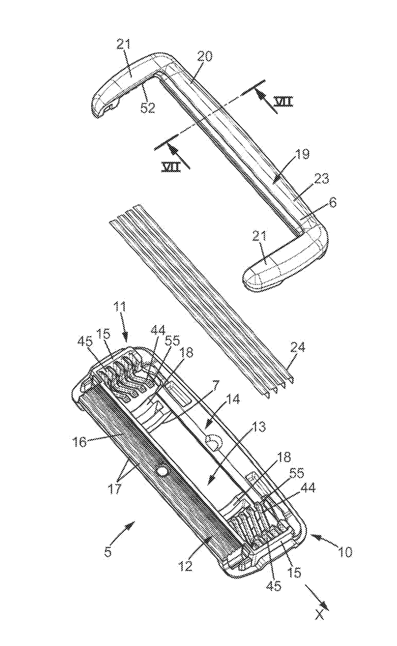
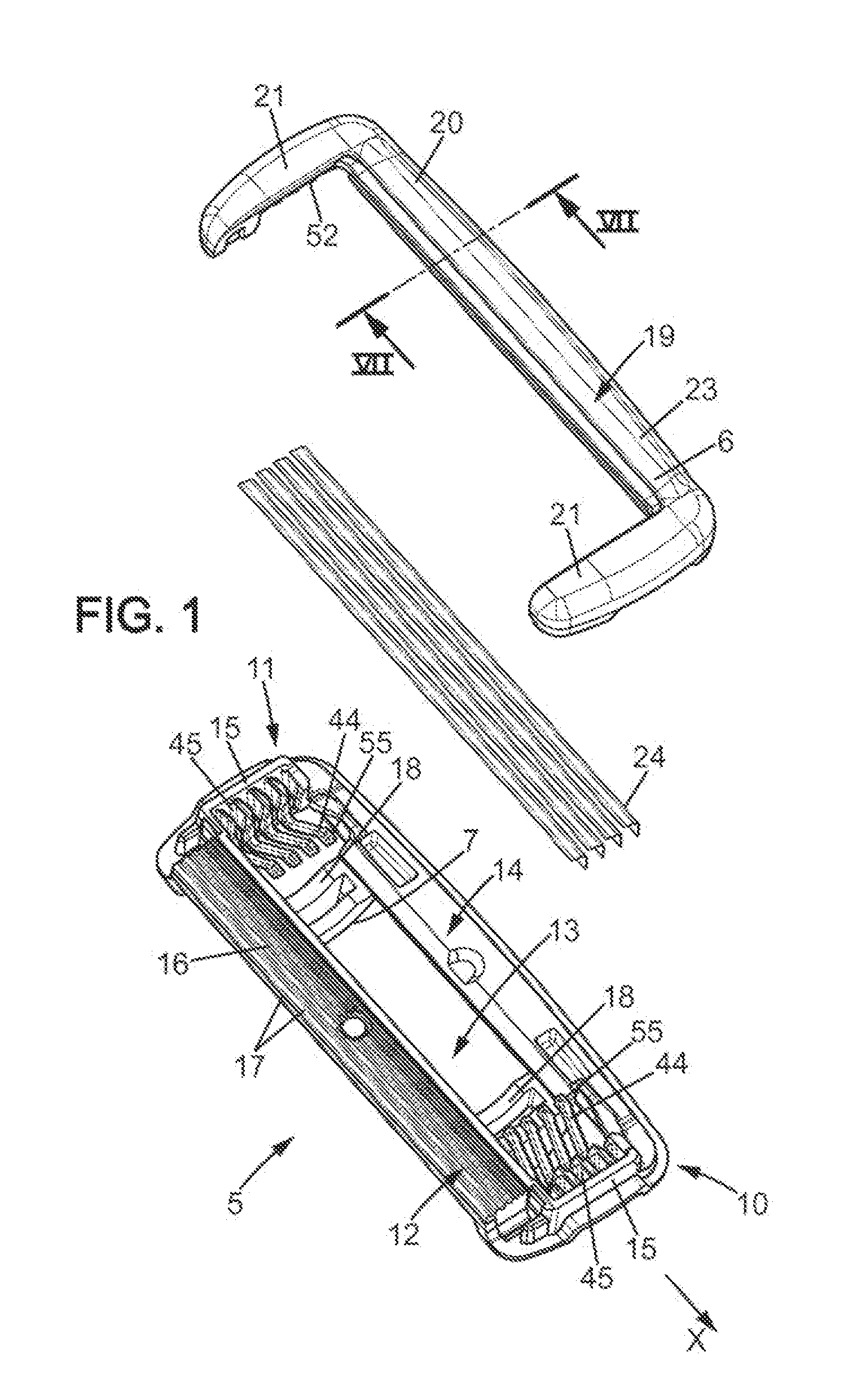
[0162]As shown on FIG. 7 below, a cutting plane (P) is defined for the head from the tangents to guard bar before the window receiving the blades and the cap behind it. Hence, upon shaving, a force will be applied to the blade by the user, along a direction F which is preferably normal to the plane (P). The blades 24 are oriented in the head 5 such that the cutting edge portion forms an angle with the cutting plane (P). In ...
PUM
Property
Measurement
Unit
Length
aaaaa
aaaaa
Length
aaaaa
aaaaa
Length
aaaaa
aaaaa
Abstract
An integrally formed rigid razor blade having a body with a cutting edge portion extending about a cutting edge portion plane, and having a cutting edge at one end, a base portion extending along a base portion plane, a bent portion intermediate the cutting edge portion and the base portion. The body is made of martensitic stainless steel that includes mainly iron and between 0.62% and 0.75% of carbon in weight.
Description
CROSS REFERENCE TO RELATED APPLICATION[0001]This application is a national stage application of International Application No. PCT / EP2012 / 069883, filed on Oct. 8, 2012, which claims the benefit of International Application No. PCT / EP2011 / 067451 filed on Oct. 6, 2011, the entire contents of both applications being incorporated herein by reference.FIELD OF THE INVENTIONS[0002]The embodiments of the present invention relate to integrally formed rigid razor blades, razor heads having such blades, and their methods of manufacture.BACKGROUND OF THE PREFERRED FIRST INVENTION[0003]In particular, the embodiments of the present invention are related to integrally formed rigid razor cutting members.[0004]In the field of mechanical wet shavers, it has long been provided with a shaver which has a head receiving one or more cutting members.[0005]Recently, the trend has been to provide cutting members which have a preferably L-shaped cross-section, with a cutting edge portion and a base portion whi...
Claims
Application Information
Patent Timeline
Application Date:The date an application was filed.
Publication Date:The date a patent or application was officially published.
First Publication Date:The earliest publication date of a patent with the same application number.
Issue Date:Publication date of the patent grant document.
PCT Entry Date:The Entry date of PCT National Phase.
Estimated Expiry Date:The statutory expiry date of a patent right according to the Patent Law, and it is the longest term of protection that the patent right can achieve without the termination of the patent right due to other reasons(Term extension factor has been taken into account ).
Invalid Date:Actual expiry date is based on effective date or publication date of legal transaction data of invalid patent.

