Complex-Shaped Piston Oil Galleries With Piston Crowns Made By Cast Metal or Powder Metal Processes

a technology of oil galleries and piston crowns, which is applied in the direction of trunk pistons, pistons, combustion engines, etc., can solve the problems of difficult cooling of bowls and rims with conventional piston galleries, new bowls designed with non-traditional or complex shapes, and high cost, so as to minimize or eliminate hot spots, uniform wall thickness

Active Publication Date: 2014-08-21
TENNECO
View PDF13 Cites 10 Cited by
  • Summary
  • Abstract
  • Description
  • Claims
  • Application Information

AI Technical Summary

Benefits of technology

[0008]The invention provides oil galleries for cast metal and powder metal pistons with complex shaped combustion bowls, as well as methods for forming such oil galleries, which provide substantially uniform wall thickness between the combustion bowls and the oil galleries. The invention minimizes or eliminates hot spots and allows the oil in the galleries to maintain the rims and other areas of the pistons and combustion bowls within acceptable temperature limits.

Problems solved by technology

The oil circulates through the gallery and cools parts of the piston which are susceptible to damage from the heat of combustion.
The upper rims around the combustion bowls are particularly susceptible to damage when overheated.
Today, however, new bowls are being designed with non-traditional or complex shapes.
However, the complex bowl shapes makes the cooling of the bowls and rims with conventional piston galleries more difficult.
Conventional machining with turning operations will not provide oil galleries with similar or corresponding complex shapes as the complex shaped combustion bowls.
If the differences in structure between the combustion bowls and the oil galleries create walls with significantly different thicknesses, or walls which are too thick to be adequately cooled by the oil being circulated in the oil galleries, then “hot spots” in the piston can occur where the material can overheat.
Hot spot areas can create weak spots in the piston where the material could crack or fail.
If a piston fails, this creates an engine failure causing major expense and perhaps a new engine for the vehicle.

Method used


Image

  • Complex-Shaped Piston Oil Galleries With Piston Crowns Made By Cast Metal or Powder Metal Processes
  • Complex-Shaped Piston Oil Galleries With Piston Crowns Made By Cast Metal or Powder Metal Processes
  • Complex-Shaped Piston Oil Galleries With Piston Crowns Made By Cast Metal or Powder Metal Processes

Examples


Embodiment Construction

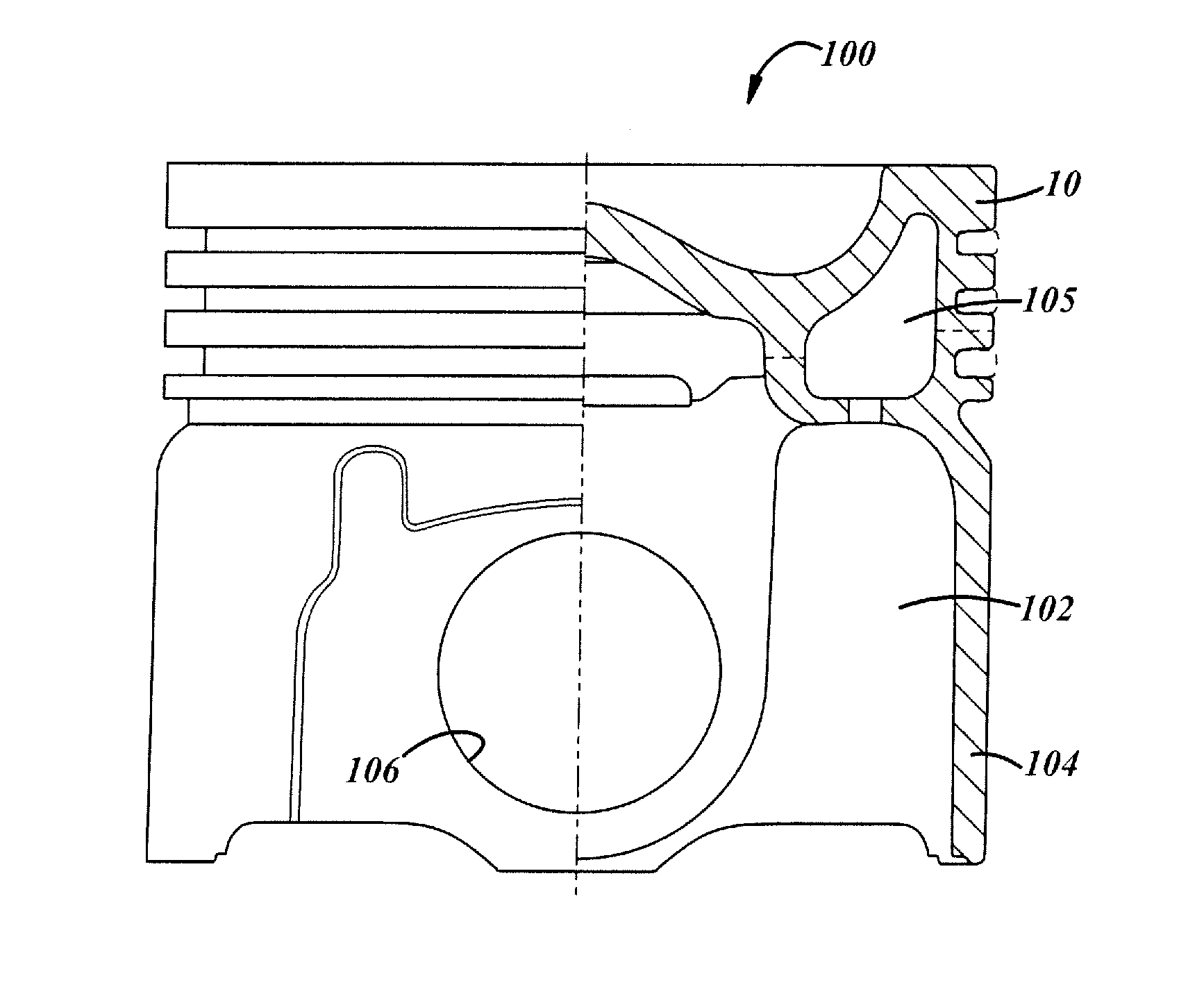
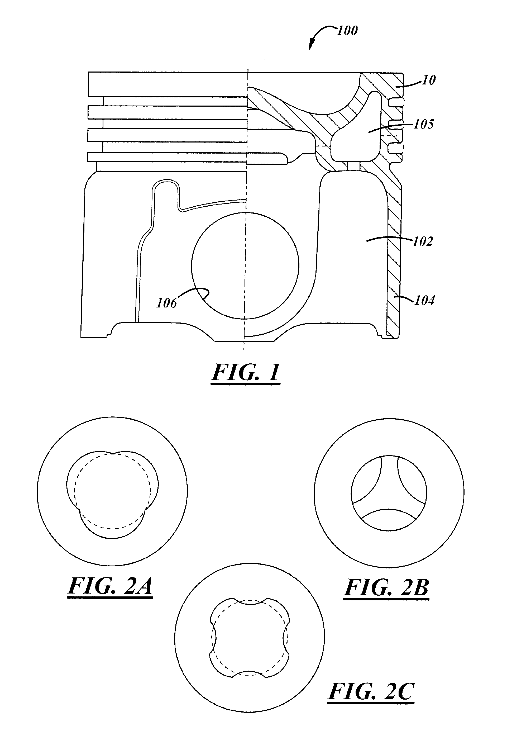
[0020]A representative piston 100 in which the present invention can be utilized if the combustion bowl has a complex shape is shown in FIG. 1. The piston 100 includes a piston crown member 10 and a lower member 102 which includes sidewalls 104 and pin bosses 106. The piston crown 10 and lower member 102 are fixedly secured together, preferably by friction welding, to form the complete piston 100.

[0021]The piston 100 has an oil gallery in which oil is circulated in order to maintain the temperature of the piston, particularly the upper surface, combustion bowl and outer rim within acceptable temperature limits. The oil gallery includes an oil gallery channel 105 positioned in the crown member 10. The oil gallery can be either opened or closed as well known in the art. If closed, the bottom wall of the oil gallery is typically included as part of the lower member 102.

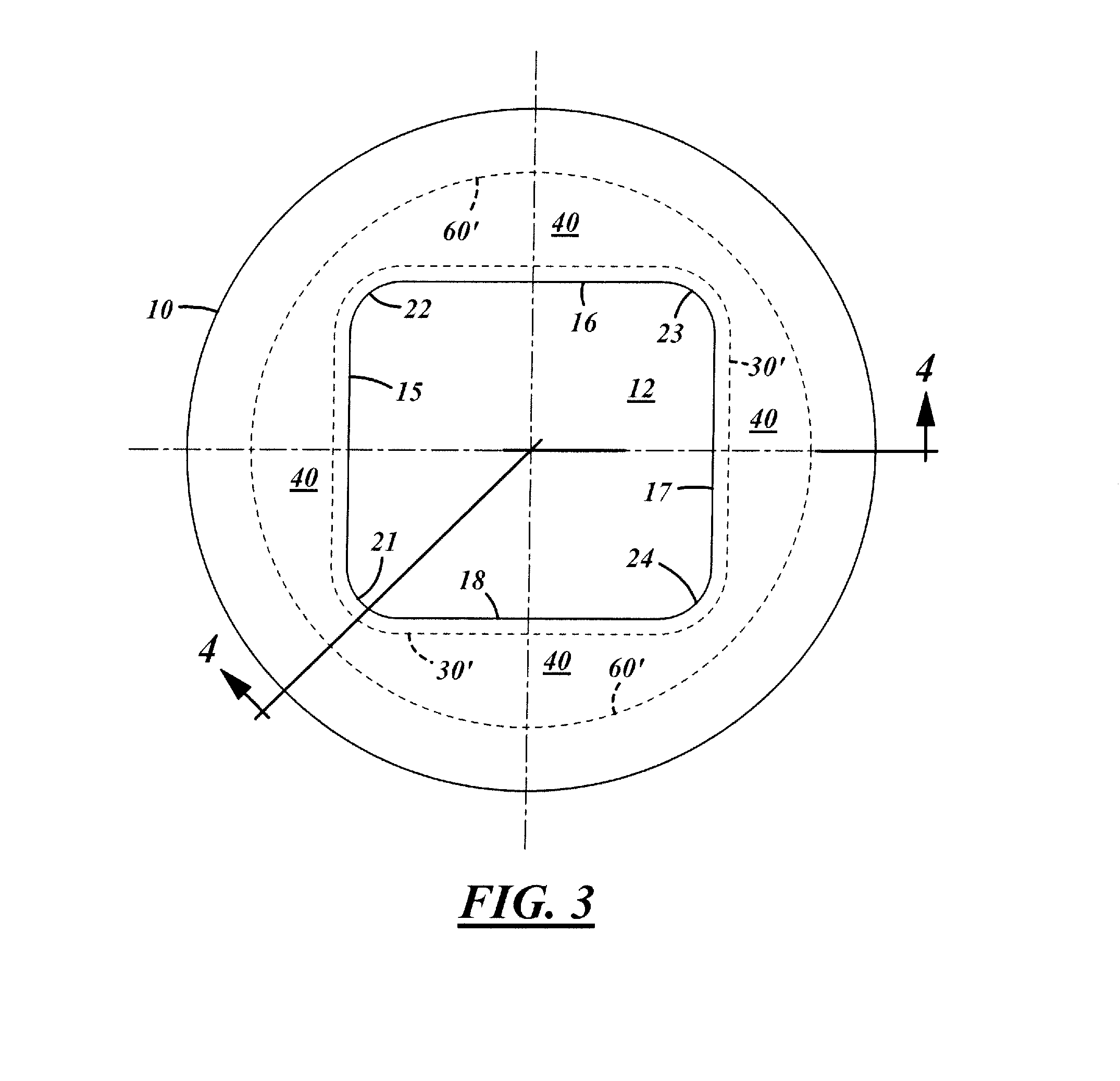
[0022]A piston crown member 10 with a representative complex combustion bowl 12 is depicted in FIG. 3. The shape of th...


PUM

PropertyMeasurementUnit
shapeaaaaaaaaaa
heataaaaaaaaaa
shapesaaaaaaaaaa

Abstract

A steel piston with an oil gallery, and process for forming a steel piston oil gallery channel, which corresponds to the complex shape of the combustion bowl in the piston crown. The piston crown is made by a cast metal or powder metal forming process. The oil gallery channel is formed to the basic shape that corresponds to the shape of the walls of the combustion bowl. Machine-turning surfaces in the oil gallery channel can be machine-finished as desired. Surfaces in the oil gallery which cannot be machined with conventional turning operations, such as recesses and protrusions into the channel, are left in the original as-formed condition.

Description

CROSS-REFERENCE TO RELATED APPLICATION[0001]This application claims the benefit of U.S. Provisional Application Ser. No. 61 / 766,055, filed Feb. 18, 2013, which is incorporated herein by reference in its entirety.TECHNICAL FIELD[0002]The invention relates generally to pistons for internal combustion engines, particularly diesel engines, and more particularly to pistons having oil galleries.BACKGROUND[0003]It is known in internal combustion engine applications, particularly with respect to diesel engines, to provide pistons with bodies formed with a closed gallery for cooling oil. The oil circulates through the gallery and cools parts of the piston which are susceptible to damage from the heat of combustion. The upper rims around the combustion bowls are particularly susceptible to damage when overheated.[0004]The cooling galleries are generally annular or ring-shaped with constant cross-sections and are provided inside the piston ring belt and adjacent the top wall and rim of the pis...

Claims


Application Information

Patent Timeline
Patent Type & Authority Applications(United States)
IPC IPC(8): F02F3/00
CPCF02F3/0015F02B23/0681F02F3/003F02F3/22Y02T10/12Y10T29/49249F02F3/26
Inventor SCHNEIDER, NORBERT G.
Owner TENNECO
Why Eureka
Try Eureka