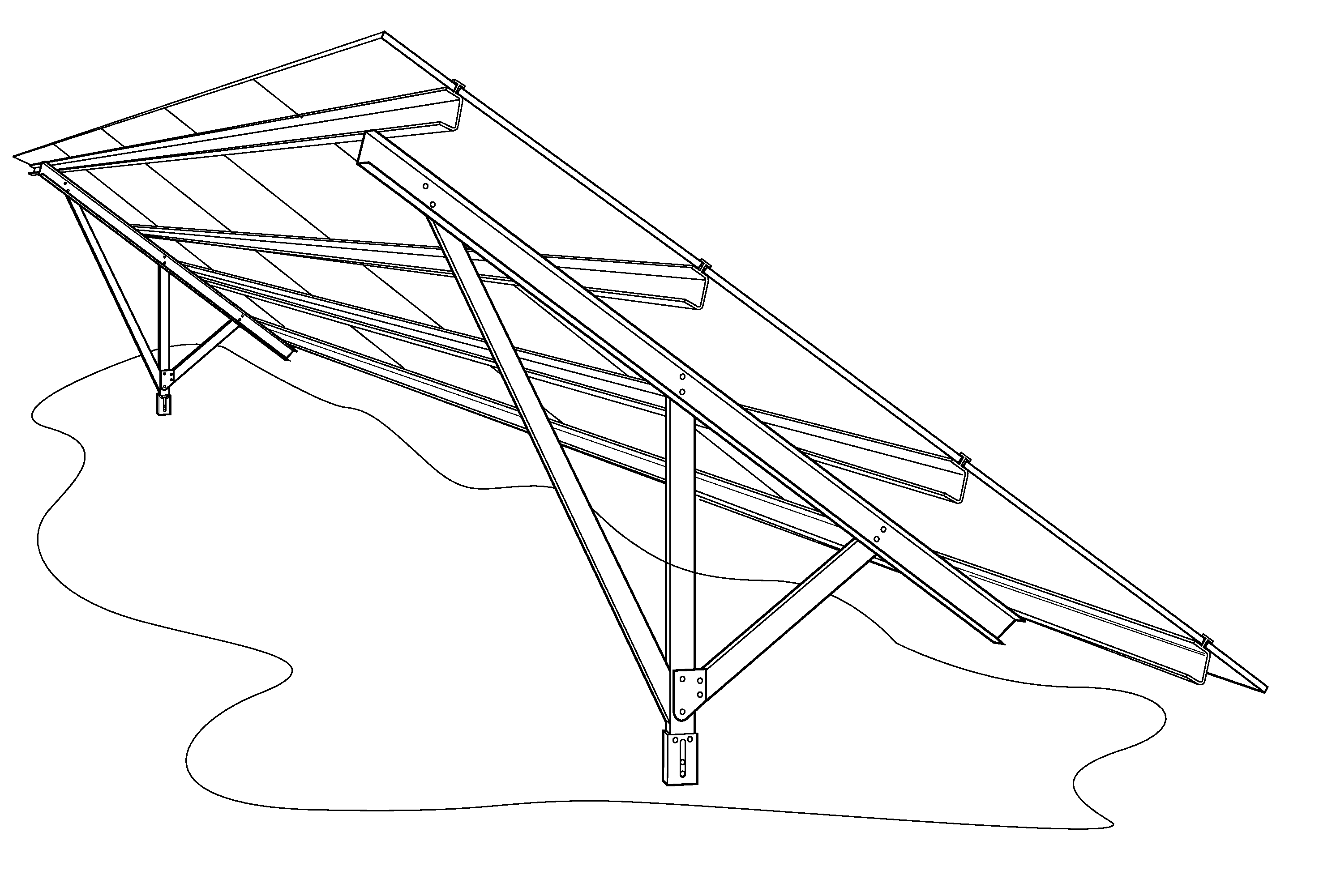
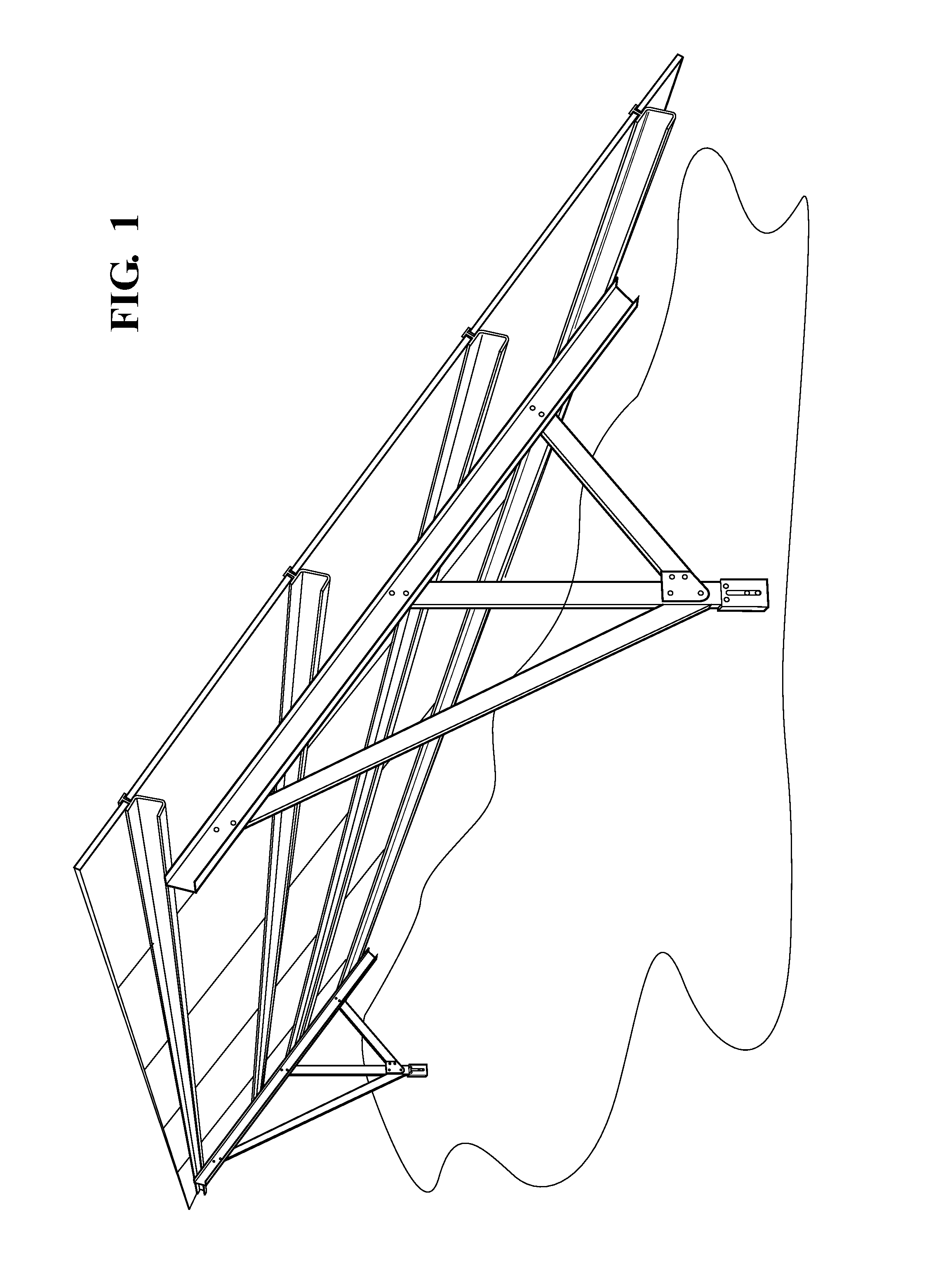
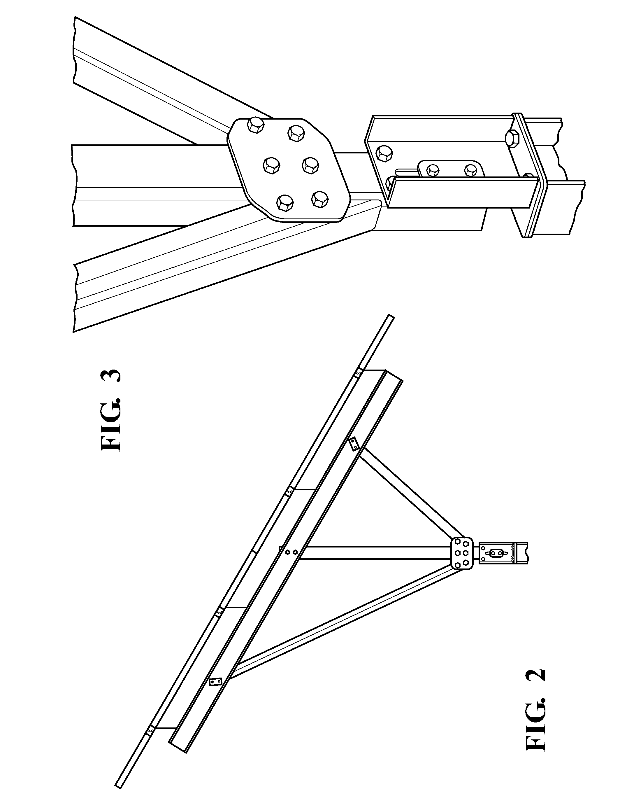
Solar Panel Assembly With A Mounting Structure

a technology of mounting structure and solar panel, which is applied in the direction of heat collector mounting/support, pv power plants, lighting and heating apparatus, etc., can solve the problems of significant and costly changes to manufacturing equipment, and achieve the effects of improving the structural integrity of the mounting structure, improving durability, and being convenient to adjus

Inactive Publication Date: 2014-08-21
MAGNA INTERNATIONAL INC
View PDF10 Cites 8 Cited by
  • Summary
  • Abstract
  • Description
  • Claims
  • Application Information

AI Technical Summary

Benefits of technology

[0011]The mounting structure of this aspect of the present invention is also advantageous because it includes fewer components than other known mounting structures. This leads to, among other things, material savings, weight savings, and labor savings during the assembly of the mounting structure in the field. Additionally, the mounting structure has very few joints which leads to improved durability. Even further, the arcuate shape of the curved member improves the structural integrity of the mounting structure. Depending on the type of connector employed to connect the north-south rail to the leg, the mounting structure may also be easier to adjust than other known mounting structures.

Problems solved by technology

In contrast, many other known mounting structures are built in the factory to orient the PV arrays at a single, non-adjustable, angle relative to the base and significant and costly changes must be made to the manufacturing equipment to produce mounting structures that support PV arrays at different angles relative to the base.

Method used


Image

  • Solar Panel Assembly With A Mounting Structure
  • Solar Panel Assembly With A Mounting Structure
  • Solar Panel Assembly With A Mounting Structure

Examples


Embodiment Construction

[0023]Referring to the Figures, wherein like numerals indicate corresponding parts throughout the several views, a first exemplary embodiment of a solar assembly 20 for harnessing potential energy from solar rays and generating electricity is generally shown in FIGS. 4-6. The solar assembly 20 includes a plurality of solar panels arranged in a plurality of arrays 22 which are supported by a stationary (i.e., non-tracking) mounting structure 24. In the exemplary embodiment, the solar panels are photovoltaic (PV) cells that are configured to receive solar radiation and convert it into electrical power. However, it should be appreciated that any other type of solar panel capable of converting potential energy from solar rays into electricity or into any other form of useable energy could alternately be employed.

[0024]Referring now to FIG. 5, the mounting structure 24 of the first exemplary embodiment includes a plurality of sub-assemblies 26 spaced from one another in a lateral directi...


PUM


Abstract

A solar assembly is provided for harnessing solar rays and generating electricity. The solar assembly includes at least one vertical leg extending in a vertical direction and having an upper attachment end. The assembly also includes at least one north-south rail and a plurality of east-west rails extending generally transversely to the north-south rail. A curved member interconnects the vertical leg with the north-south rail and extends through an arcuate shape. The solar assembly also includes a plurality of generally flat arrays of solar panels, such as photovoltaic panels, are coupled to the east-west members. The orientation of the solar panels relative to a base or the ground is dependent on the location along the curved member of the connection with the vertical leg.

Description

CROSS-REFERENCE TO PRIOR APPLICATION[0001]This U.S. National Stage Patent application claims the benefit of International Application Serial No. PCT / US2012 / 059964 filed Oct. 12, 2012 entitled “Solar Panel Assembly With A Mounting Structure,” which claims the benefit of U.S. Provisional Patent Application Ser. No. 61 / 547,147 filed Oct. 14, 2011, entitled “Mounting Structure,” the entire disclosures of the applications being considered part of the disclosure of this application and hereby incorporated by reference.BACKGROUND OF THE INVENTION[0002]1. Field of the Invention[0003]The subject invention is related to a solar panel assembly, and more precisely to a solar panel assembly including a mounting structure for solar panels.[0004]2. Description of the Prior Art[0005]Solar power is becoming an increasingly popular alternative to fossil fuels for generating electricity. In general, solar power generators harness the potential energy of solar radiation and convert that potential energ...

Claims


Application Information

Patent Timeline
Patent Type & Authority Applications(United States)
IPC IPC(8): H01L31/042
CPCH02S20/00H01L31/0422F24S25/12F24S25/70F24S2025/6005H02S20/10H02S20/30Y02B10/10Y02E10/47Y02E10/50
Inventor WERNER, MARK F.MARTEN, ZACHARY A.SZADYR, PETER M.WARPUP, RYAN R.
Owner MAGNA INTERNATIONAL INC
Why Eureka
Try Eureka