Method and apparatus for measurement of neural response

a neural response and measurement method technology, applied in the field of neural response measurement, can solve the problems of difficult task, impracticality of implant system, and inability to precisely understand the mechanism involved, so as to slow and reduce the neural conduction velocity

Inactive Publication Date: 2014-08-21
SALUDA MEDICAL PTY LTD
View PDF11 Cites 68 Cited by
  • Summary
  • Abstract
  • Description
  • Claims
  • Application Information

AI Technical Summary

Benefits of technology

[0020]Some embodiments of the invention may further provide for estimating from the conduction velocity of the neural response, or from changes in the conduction velocity of the neural response as detected from one measurement to a next measurement, an approximate proportion of fibre classes recruited to produce the neural response. For example, in such embodiments, a high conduction velocity may be taken as being indicative of recruitment of large fibres such as Aβ fibres. Similarly, an increased conduction velocity from one measurement to a next measurement may be taken as being indicative of increased recruitment of large fibres such as Aβ fibres. Such embodiments may be particularly useful in feedback control of an applied stimulus in order to preferentially recruit Aβ fibres to achieve beneficial therapeutic effects while minimizing recruitment of smaller fiber classes to avoid adverse side effects.
[0026]In some embodiments of the third aspect of the invention, the disease may be diabetes mellitus. Diabetes mellitus reversibly slows the neural conduction velocity in patients having insufficient metabolic control, so that detection of reductions in neural conduction velocity may assist in diagnosing the onset, state or progression of diabetes mellitus, and may for example trigger revision of a treatment schedule.
[0027]In some embodiments of the third aspect of the invention, the disease may be central sensitization. Central sensitization tends to reduce the neural conduction velocity, so that detection of reductions in neural conduction velocity may assist in diagnosing the onset, state or progression of central sensitization. In such embodiments, a conduction velocity map of the spinal cord may be obtained by progressively applying stimuli using each of a plurality of electrodes of an implanted electrode array, and using spaced apart measurement electrodes to obtain a measure of the conduction velocity resulting from each stimulus site. Mapping conduction velocity against location then will give an indication of the location(s) at which central sensitization has occurred. Such a map may then be used to optimize the location of therapeutic stimuli, either through a manual fitting of the device or through an automated feedback procedure carried out by an implanted control unit.

Problems solved by technology

While the clinical effect of spinal cord stimulation (SCS) is well established, the precise mechanisms involved are poorly understood.
However, this can be a difficult task as an observed CAP signal will typically have a maximum amplitude in the range of microvolts, whereas a stimulus applied to evoke the CAP is typically several volts.
To resolve a 10 μV spinal cord potential (SCP) with 1 μV resolution in the presence of an input 5V stimulus, for example, requires an amplifier with a dynamic range of 134 dB, which is impractical in implant systems.

Method used


Image

  • Method and apparatus for measurement of neural response
  • Method and apparatus for measurement of neural response
  • Method and apparatus for measurement of neural response

Examples


Embodiment Construction

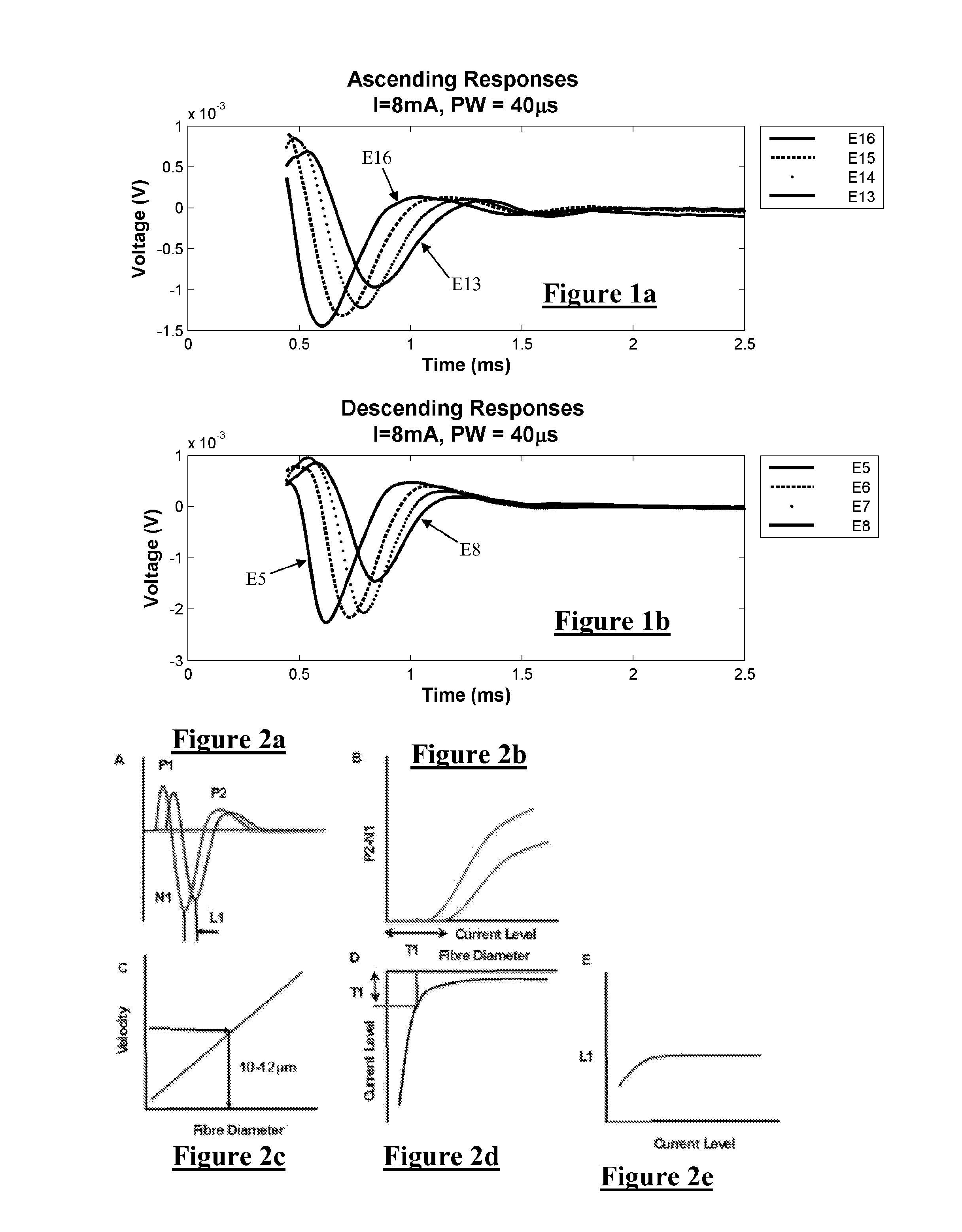
[0044]FIG. 1 illustrates measured compound action potentials in the sheep spinal cord, both in the ascending / rostral direction (FIG. 1a) and descending / caudal direction (FIG. 1b). According to current theory the fibres responsible for inhibition of pain in therapeutic SCS are the Aβ fibres in the dorsal horn. Stimulation of these fibres produces an orthodromic (ascending) volley of discharges, and also an antidromic descending volley. In FIG. 1a, a single ascending compound action potential (CAP) is measured as it passes 4 measurement electrodes (E13 through E16) which are spaced apart along the neural pathway, increasingly distant from the stimulus. In FIG. 1b, a single descending CAP is measured as it passes 4 measurement electrodes (E5 through E8) which are spaced apart along the neural pathway, increasingly distant from the stimulus.

[0045]As can be seen in FIG. 1, in both the orthodromic and antidromic directions, the further away the measurement electrode is from the stimulus s...


PUM


Abstract

A method for estimating conduction velocity of a neural response. Measurements of the neural response are obtained from at least two electrodes which are at distinct locations along a neural pathway. A delay between the time of arrival of the neural response at each respective electrode is determined from the measurements. From the delay, and from knowledge of electrode spacing, a conduction velocity of the neural response is estimated.

Description

CROSS-REFERENCE TO RELATED APPLICATIONS[0001]This application claims the benefit of Australian Provisional Patent Application No. 2011901822 filed 13 May 2011, Australian Provisional Patent Application No. 2011901817 filed 13 May 2011 and Australian Provisional Patent Application No. 2011901824 filed 13 May 2011, each of which are incorporated herein by reference.TECHNICAL FIELD[0002]The present invention relates to measurement of a neural response to a stimulus, and in particular relates to measurement of a compound action potential by using one or more electrodes implanted proximal to the neural pathway.BACKGROUND OF THE INVENTION[0003]There are a range of situations in which it is desirable to measure a compound action potential (CAP). For example, neuromodulation is used to treat a variety of disorders including chronic pain, Parkinson's disease, and migraine. A neuromodulation system applies an electrical pulse to tissue in order to generate a therapeutic effect. When used to r...

Claims


Application Information

Patent Timeline
Patent Type & Authority Applications(United States)
IPC IPC(8): A61B5/04A61N1/04A61N1/05A61B5/00
CPCA61B5/04001A61N1/05A61N1/0456A61B5/40A61B5/4041A61N1/0551A61N1/36071A61N1/36135A61B5/24
Inventor PARKER, JOHN LOUISKARANTONIS, DEAN MICHAEL
Owner SALUDA MEDICAL PTY LTD
Why Eureka
Try Eureka