Wire electric discharge machine and calculation method for wire support positions of wire electric discharge machine

Active Publication Date: 2014-08-21
FANUC CORP
View PDF6 Cites 13 Cited by
  • Summary
  • Abstract
  • Description
  • Claims
  • Application Information

AI Technical Summary

Benefits of technology

The present invention is about a wire electric discharge machine that can correct its taper angle by using a contact detector. This correction is done automatically and takes into account the machine's measurements without the need for an external instrument. The result is a more accurate and efficient wire support system.

Problems solved by technology

If electric discharge machining of a workpiece is performed actually, the bending of the wire electrode is increased due to discharge heat, error is included in the taper angle, and the machining precision degrades.
In addition, measurement of the workpiece is not made on the electric discharge machine, so additional machining or subsequent finishing is not supported.
Accordingly, the prior art technique is inconvenient in that a measuring instrument is required separately from a wire electric discharge machine and a correction value needs to be calculated according to a mathematical expression.
This makes it very difficult to perform re-machining such as modification after measurement.

Method used


Image

  • Wire electric discharge machine and calculation method for wire support positions of wire electric discharge machine
  • Wire electric discharge machine and calculation method for wire support positions of wire electric discharge machine
  • Wire electric discharge machine and calculation method for wire support positions of wire electric discharge machine

Examples


Embodiment Construction

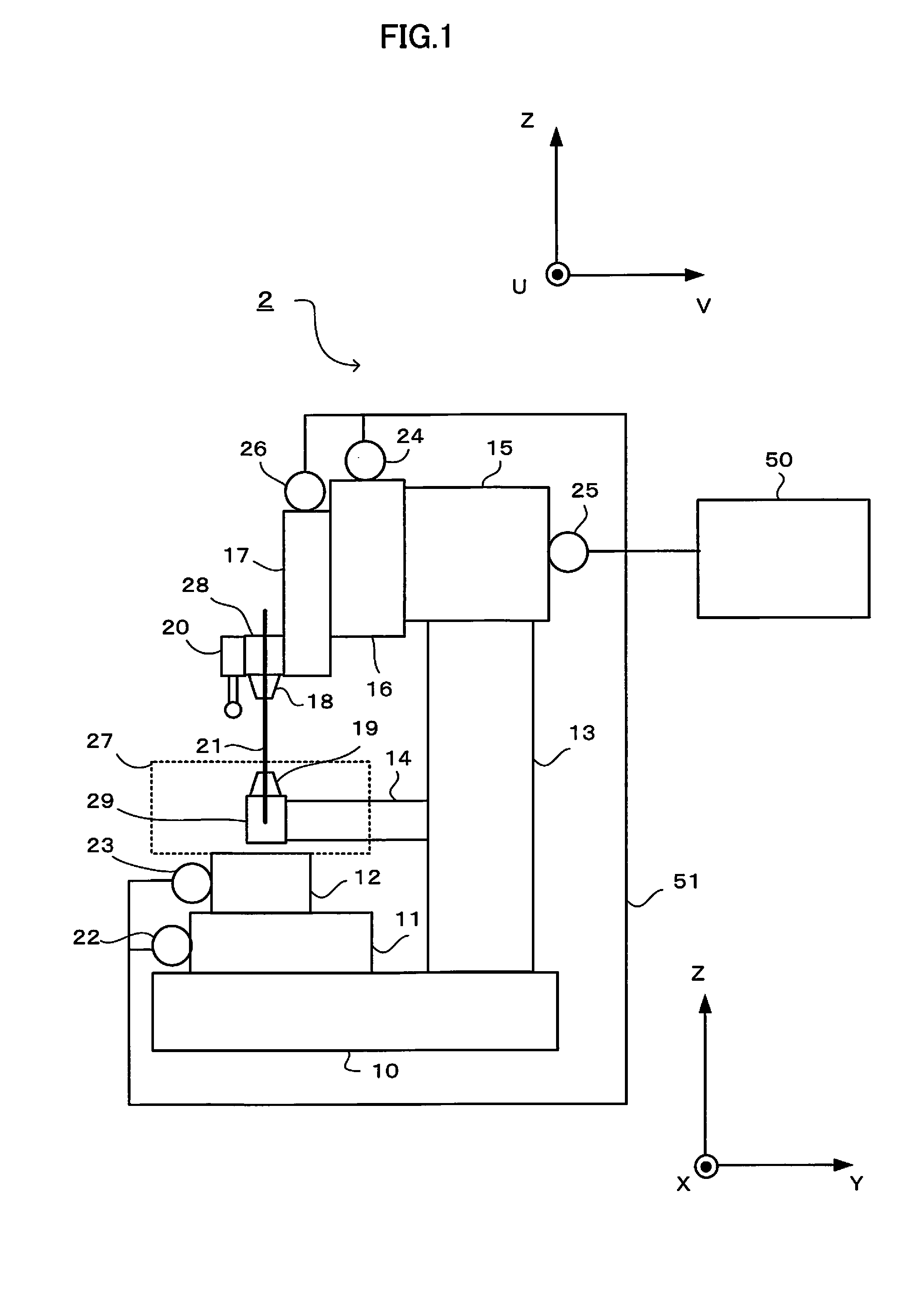
[0029]FIG. 1 shows the structure of a wire electric discharge machine according to an embodiment of the present invention.

[0030]A wire electric discharge machine 2 machines a workpiece by generating discharge between a wire electrode 21 and the workpiece to be machined. The wire electric discharge machine 2 includes an X-axis saddle 11 on a bed 10, which moves in the X-axis direction when driven by an X-axis motor 22. The wire electric discharge machine 2 further includes a Y-axis table 12 on an X-axis saddle 11, which moves in the Y-axis direction when driven by a Y-axis motor 23. A work tank 27, which incorporates a workpiece mount (not shown) on which the workpiece is placed, is secured to the Y-axis table 12.

[0031]The column 13 extends vertically from the bed 10. The column 13 has a V-axis saddle 15 thereon. The V-axis saddle 15 moves in the V-axis direction when driven by the V-axis motor 25. The V-axis direction is the same as the Y-axis direction. A U-axis saddle 16 is attach...


PUM

PropertyMeasurementUnit
Angleaaaaaaaaaa

Abstract

One arbitrary point on an upper surface of a workpiece and two points at arbitrary heights on a tapered section of the workpiece are measured using a contact detector disposed on an upper wire guide of a wire electric discharge machine to calculate the shape accuracy and tapered angle. Based on the calculated data, the upper and lower wire guide support positions of the upper and lower wire guides are calculated. Using the calculated upper and lower wire guide support positions, electric discharge machining is performed on the workpiece.

Description

BACKGROUND OF THE INVENTION[0001]1. Field of the Invention[0002]The present invention relates to a wire electric discharge machine having a taper angle correction function using a contact detector and a calculation method for wire support positions of a wire electric discharge machine.[0003]2. Description of the Related Art[0004]When a taper machining is performed on a workpiece by a wire electric discharge machine, the wire support positions of the upper and lower wire guides for supporting the wire electrode are measured by a jig or the like through short-circuit detection of the wire electrode, and the measured wire support positions are set in the controller.[0005]A known technique for correcting the angle of a wire electrode is disclosed in Japanese Patent Application Laid-Open No. 2000-24839. In this technique, the taper angle is corrected through contact of a wire electrode by using a specific jig without performing machining actually. Another known technique for automaticall...

Claims


Application Information

Patent Timeline
IPC IPC(8): G05B19/18
CPCG05B19/182B23H7/065B23H2500/20
Inventor NISHIKAWA, RYOUTAKAHASHI, SHOUJI
Owner FANUC CORP
Why Eureka
Try Eureka