Radiographic image capturing apparatus and radiographic image capturing system

a technology of radiographic image and capturing apparatus, which is applied in the direction of optical radiation measurement, television system, instruments, etc., can solve the problems of inability to correctly readout image data d, inability to achieve and inability to achieve the establishment of an interface between the two

Active Publication Date: 2014-08-28
KONICA MINOLTA INC
View PDF12 Cites 6 Cited by
  • Summary
  • Abstract
  • Description
  • Claims
  • Application Information

AI Technical Summary

Benefits of technology

[0011]An object of the present invention, which has been made to solve such problems, is to provide a radiographic image capturing apparatus and a radiographic image capturing system including a radiographic image capturing apparatus which can detect the irradiation of radiatio

Problems solved by technology

If the manufacturers of the radiation generator 55 and the radiographic image capturing apparatus are different, the establishment of an interface therebetween is not always readily achievable or may be unachievable.
Such a trouble in coordination between the radiation generator 55 and the radiographic image capturing apparatus may cause an overlap bet

Method used


Image

  • Radiographic image capturing apparatus and radiographic image capturing system
  • Radiographic image capturing apparatus and radiographic image capturing system
  • Radiographic image capturing apparatus and radiographic image capturing system

Examples


first embodiment

[Structure and Other Details of Radiographic Image Capturing Apparatus]

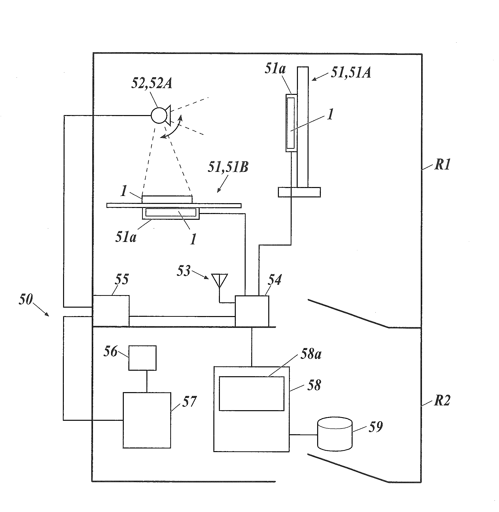
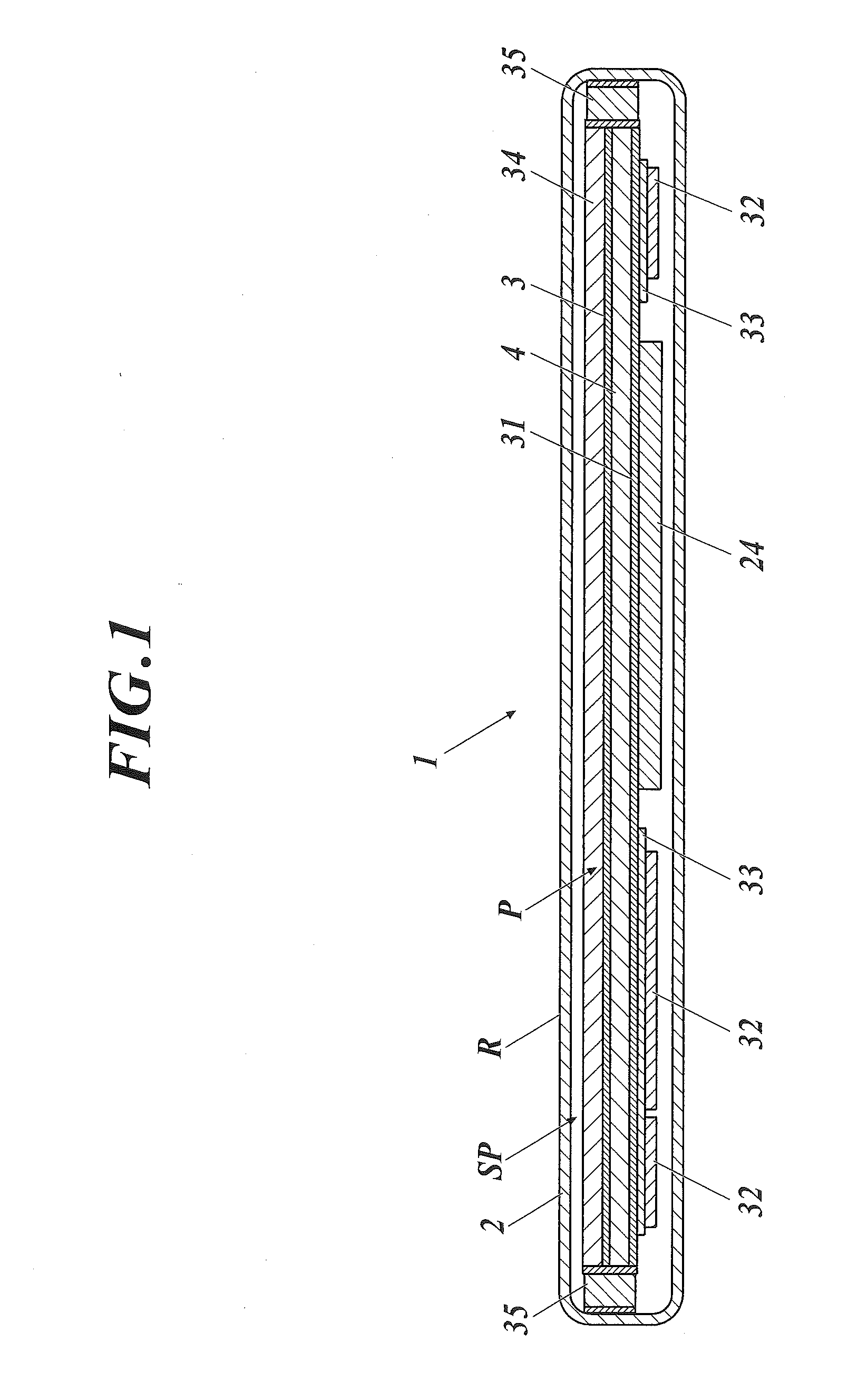
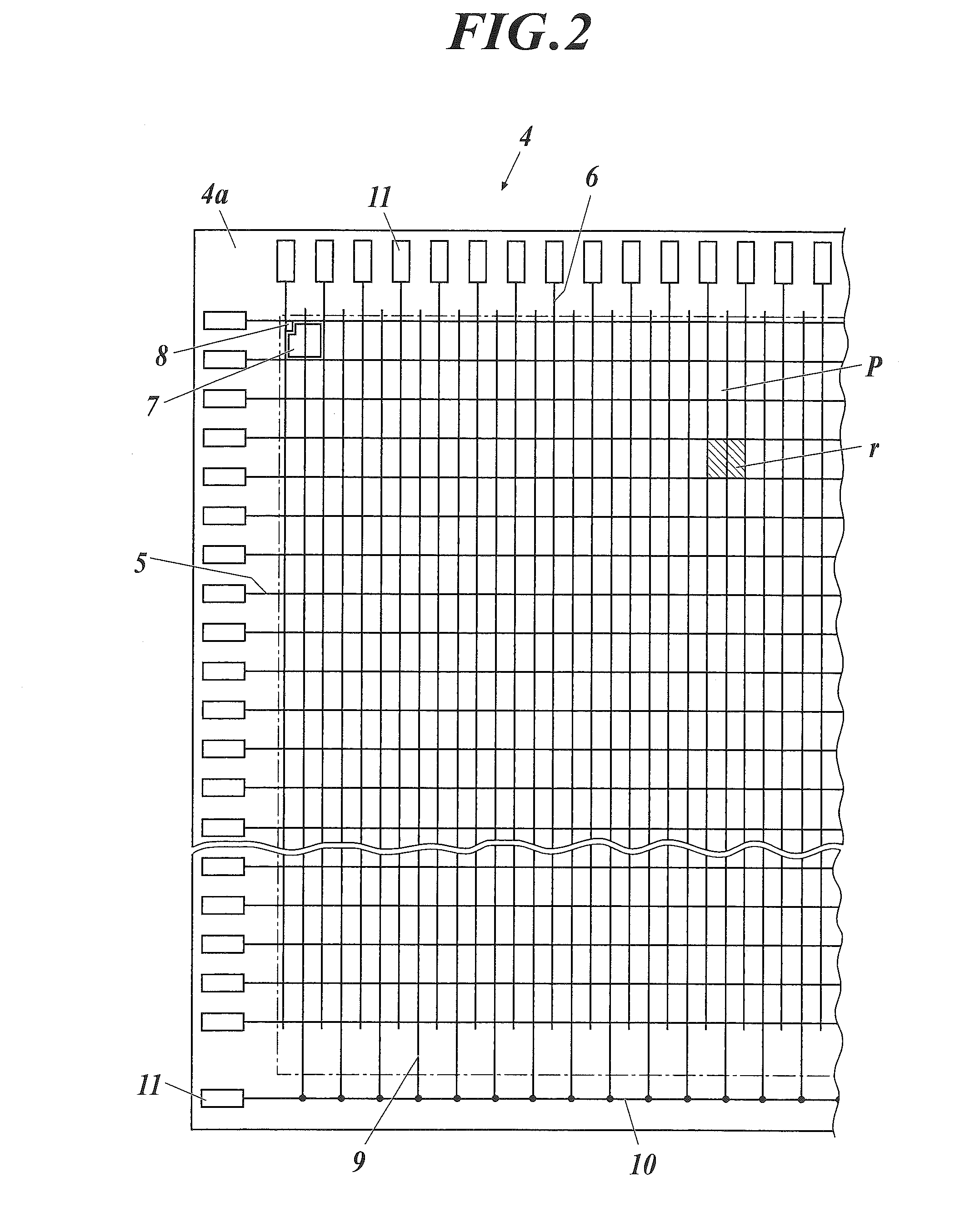
[0058]The structure and other details of a radiographic image capturing apparatus of this embodiment will be described. FIG. 1 is a cross-sectional view of the radiographic image capturing apparatus of this embodiment. FIG. 2 is a plan view illustrating the structure of a substrate of the radiographic image capturing apparatus. In FIGS. 1 and 2 and other drawings, the components in the apparatus are not always accurately expressed in relative size, position, or other respects as in the actual apparatus. In the following description, “above” or “below”, i.e., an expression associated with the vertical direction is relative to a radiographic image capturing apparatus 1 disposed on a virtual horizontal plane. Accordingly, when the radiographic image capturing apparatus 1 is used in an upright posture (for example, when the radiographic image capturing apparatus 1 is mounted in a Bucky unit 100 for capturing in a sta...

second embodiment

[0115]In the first embodiment, the radiographic image capturing apparatus 1 can detect both the start and end of the irradiation with radiation from the radiation generator 55. Alternatively, the radiographic image capturing apparatus 1 may detect only one of the start or end of such irradiation with radiation.

[0116]To address such a situation, a radiographic image capturing apparatus 1 of the present invention will now be described that can detect only one of the start and end of such irradiation. Functional components common to the first and second embodiments are represented by the same reference numerals. In the second embodiment, for convenience of explanation, the radiographic image capturing apparatus 1 can detect only the end of the irradiation with radiation. The precise timing of the shortening of the readout time TRO is not always detectable; hence, the readout time TRO is set to a minimum value, i.e., the interval ΔT (see FIG. 6) is set to 0 in advance (this operation is...

third embodiment

[0122]In the third embodiment, the radiographic image capturing apparatus 1 can detect only the start of the irradiation with radiation.

[0123]In this embodiment, the controller 22 in the radiographic image capturing apparatus 1 cannot detect the timing of the end of the irradiation of radiation from the radiation generator 55, and thus determines whether the standby time τ (from the end of the current readout of the image data D to the start of the readout of the image data D in the next capturing) is adjusted, based on the period (period T1 which corresponds to the first period T1 in the first embodiment) from the end of the readout of image data D to the start of irradiation with radiation.

[0124]As described above, a reduction in the period T1 (see FIG. 8B, for example) may cause the start of irradiation with radiation during the readout of the image data D. The standby time τ is reduced to avoid such a phenomenon. This increases the period T1 for the next capturing. In contrast, ...


PUM


Abstract

A radiographic image capturing apparatus and a radiographic image capturing system are shown. According to one aspect, the radiographic image capturing apparatus includes the following. A scanning driving unit applies voltage to scanning lines. A switching element releases electric charge upon application of the ON-state voltage. A readout circuit converts the electric charge into image data and reads the data. A controller reads the image data. The detecting unit detects start and end of irradiation based on a change in a signal. The controller determines whether a standby time from end of readout to start of readout in next capturing is changed with reference to a first period and a second period. The first period ranges from end of readout to detection of start of irradiation. The second period ranges from detection of end of irradiation to start of readout.

Description

CROSS REFERENCE TO RELATED APPLICATIONS[0001]The present invention claims priority under 35 U.S.C. §119 to Japanese Application No. 2013-038073, filed Feb. 28, 2013, the entire content of which is incorporated herein by reference.BACKGROUND[0002]1. Field of the Invention[0003]The present invention relates to a radiographic image capturing apparatus and a radiographic image capturing system, particularly to a radiographic image capturing apparatus that can capture serial images, such as moving images, of a subject and a radiographic image capturing system including the radiographic image capturing apparatus.[0004]2. Description of Related Art[0005]Radiographic image capturing apparatuses using flat panel detectors (FPDs) are well known. Traditional radiographic image capturing apparatuses have integrated supports and are used for particular purposes. In recent years, portable radiographic image capturing apparatuses including radiation detectors in housing so as to be portable have b...

Claims


Application Information

Patent Timeline
IPC IPC(8): G01T1/172
CPCG01T1/172H04N5/32G01T1/247H04N25/63H04N25/75
Inventor SAKINO, KAZUHIRO
Owner KONICA MINOLTA INC
Why Eureka
Try Eureka