Downhole electromagnetic and mud pulse telemetry apparatus

a telemetry apparatus and electromagnetic technology, applied in the field of downhole telemetry, can solve the problems of incompatibility of mp telemetry systems with air/underbalance drilling, mp telemetry systems tend to provide generally slower baud rates and more narrow bandwidths, and mp telemetry systems tend to provide more narrow bandwidths

Active Publication Date: 2014-08-28
EVOLUTION ENG
View PDF2 Cites 43 Cited by
  • Summary
  • Abstract
  • Description
  • Claims
  • Application Information

AI Technical Summary

Benefits of technology

[0017]According to another aspect of the invention there is provided a downhole telemetry tool comprising: sensors for acquiring downhole measurement data; an electromagnetic (EM) telemetry unit; a mud pulse (MP) telemetry unit; at least one control module communicative with the sensors and EM and MP telemetry units and comprising a processor and a memory having encoded thereon program code executable by the processor to perform any of the above methods, wherein steps of transmitting the first, second or third EM signals are carried out by the EM telemetry unit, and the steps of transmitting the first, second or third MP telemetry signals are carried out by the MP telemetry unit. The sensors can comprise drilling conditions sensors and directional and inclination (D&I) sensors. The drilling conditions sensors can comprise an axial and lateral shock sensor, an RPM gyro sensor and a flow switch sensor. The D&I sensors can include a three axis accelerometer, a three axis magnetometer, and a gamma sensor, and back-up sensors.
[0018]The telemetry tool can further comprise multiple control modules and a communications bus in communication with each of the multiple control modules. The multiple control modules include a control sensor control module communicative with the drilling conditions sensors, an interface control module communicative with the D&I sensors, an EM control module communicative with the EM telemetry unit, an MP control module communicative with the MP telemetry unit, and a power management control module. The control sensor control module can comprise a processor and a memory having encoded thereon program code executable by the processor to decode downlink command instructions from a downlink command signal received by one of the drilling conditions sensors, and to transmit the downlink command instructions to other control modules via the communications bus. The EM control module, MP control module and interface control module can each comprise a processor and a memory; each memory of each control module contains at least a portion of each configuration file in the set of configuration files.
[0019]The sensors can further comprise a pressure sensor communicative with the power management control module. The power management control module can comprise a processor and a memory having encoded thereon program code executable by the processor to decode downlink command instructions from a pressure downlink command signal received by the pressure sensor and to transmit the downlink command instructions to the other control modules via the communications bus.
[0020]The downlink command instructions can comprise a selected configuration file from the set of configuration files, in which case each memory of each control module comprises program code to execute the portion of the selected configuration file contained in the respective memory.

Problems solved by technology

However, MP telemetry systems tend to provide generally slower baud rates and more narrow bandwidths compared to EM telemetry, and require mud to be flowing in order for telemetry to be transmitted.
Thus, MP telemetry systems are incompatible with air / underbalanced drilling, which is a growing market in North America.
However, EM telemetry systems can be incompatible with some formations such as formations containing high salt content or formations of high resistivity contrast.
These limitations create challenges with battery life and lowered data rate transmission in the downhole MWD tool.
However, such known combined telemetry systems are relatively underdeveloped, and for instance, often simply stack a known EM tool and a known MP tool in series with minimal system integration.
Such known combined telemetry systems also do not feature sophisticated data management between the EM and MP telemetry tools, and thus are not optimized for performance, reliability, and efficient power consumption.

Method used


Image

  • Downhole electromagnetic and mud pulse telemetry apparatus
  • Downhole electromagnetic and mud pulse telemetry apparatus
  • Downhole electromagnetic and mud pulse telemetry apparatus

Examples


Embodiment Construction

Overview

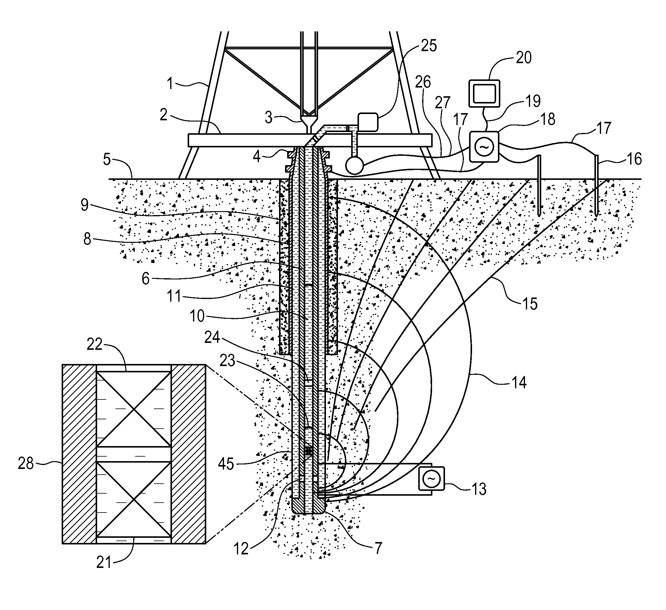
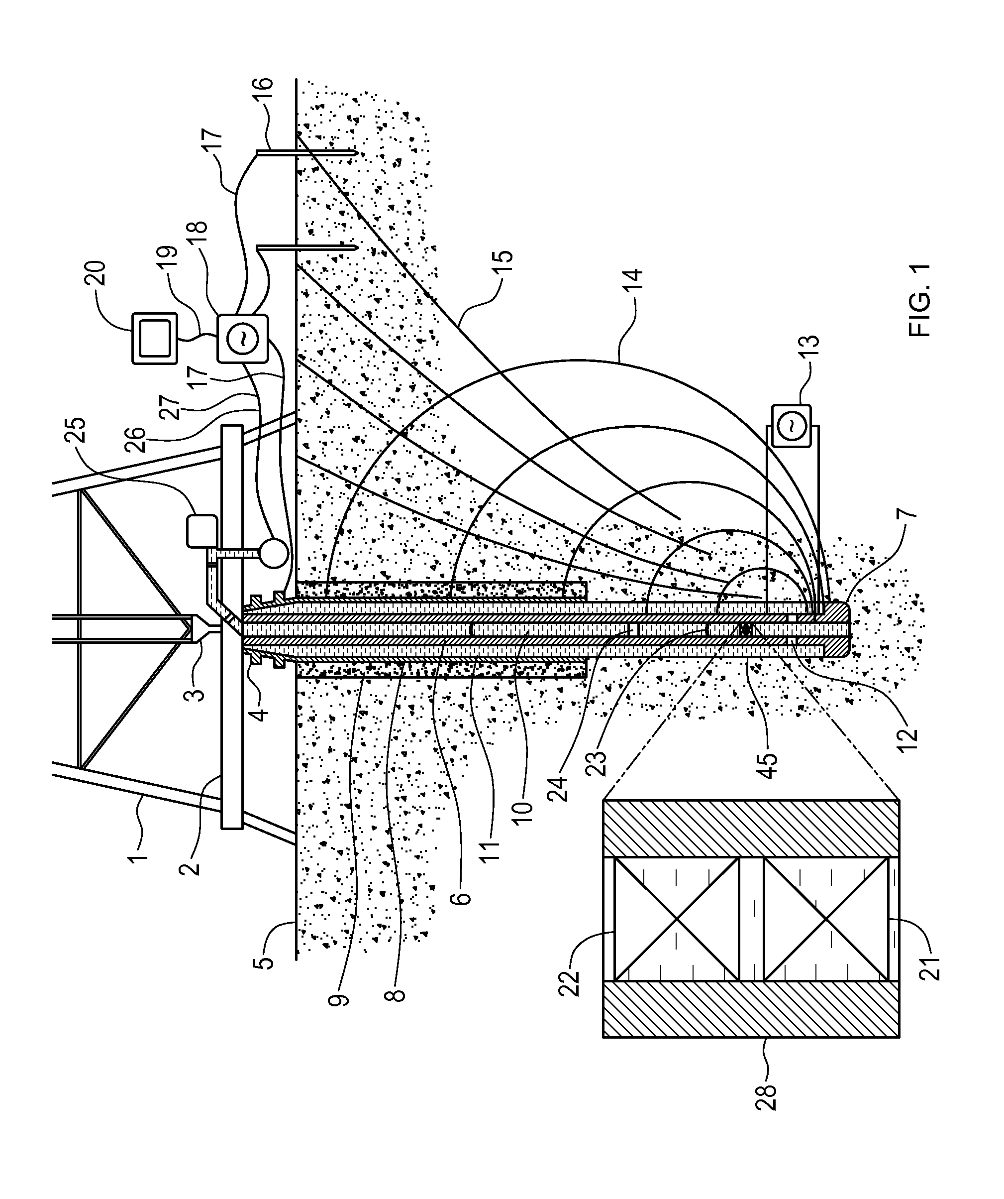
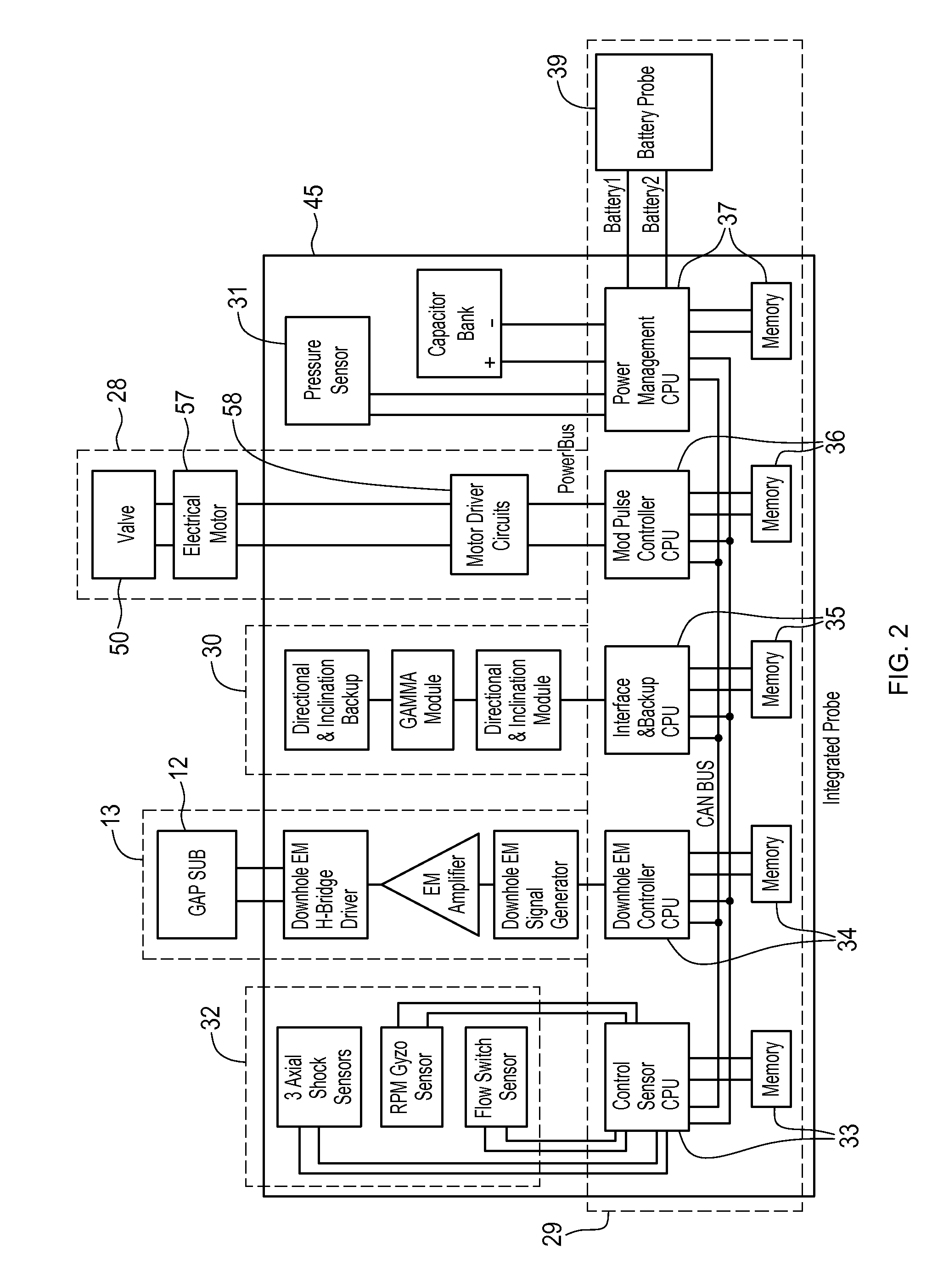
[0034]Embodiments of the present invention described herein relate to a MWD telemetry system comprising a downhole MWD telemetry tool comprising a MP telemetry unit and an EM telemetry unit. The MWD telemetry tool can be configured to transmit data in an EM-only telemetry mode using only the EM telemetry unit, in an MP-only mode using only the MP telemetry unit, or in a concurrent telemetry mode using both the EM and MP telemetry units concurrently. When transmitting data in the concurrent telemetry mode, the telemetry tool can be configured to transmit in a concurrent confirmation mode wherein the same telemetry data is transmitted by each of the EM and MP telemetry units, or in a concurrent shared mode wherein some of the telemetry data is transmitted by the EM telemetry unit, and the rest of the telemetry data is transmitted by the MP telemetry unit. The telemetry tool can be programmed to start operating using a selected telemetry mode, and change its operating telemetry...


PUM


Abstract

A measurement-while-drilling (MWD) telemetry system comprises a downhole MWD telemetry tool comprising a mud pulse (MP) telemetry unit and an electromagnetic (EM) telemetry unit. The MWD telemetry tool can be configured to transmit data in an EM-only telemetry mode using only the EM telemetry unit, in an MP-only mode using only the MP telemetry unit, or in a concurrent telemetry mode using both the EM and MP telemetry units concurrently. When transmitting data in the concurrent telemetry mode, the telemetry tool can be configured to transmit in a concurrent confirmation mode wherein the same telemetry data is transmitted by each of the EM and MP telemetry units, or in a concurrent shared mode wherein some of the telemetry data is transmitted by the EM telemetry unit, and the rest of the telemetry data is transmitted by the MP telemetry unit. The telemetry tool can be programmed to change its operating telemetry mode in response to a downlink command sent by an operator at surface.

Description

CROSS-REFERENCE TO RELATED APPLICATION[0001]This application claims the benefit under 35 U.S.C. §119 of U.S. Application No. 61 / 769,033 filed 25 Feb. 2013 and entitled DOWNHOLE ELECTROMAGNETIC AND MUD PULSE TELEMETRY APPARATUS which is hereby incorporated herein by reference for all purposes.FIELD[0002]This invention relates generally to downhole telemetry, and in particular to a downhole electromagnetic and mud pulse telemetry apparatus.BACKGROUND ART[0003]The recovery of hydrocarbons from subterranean zones relies on the process of drilling wellbores. The process includes drilling equipment situated at surface, a drill string extending from the surface equipment to the formation or subterranean zone of interest. The drill string can extend thousands of metres below the surface. The terminal end of the drill string includes a drill bit for drilling (or extending) the wellbore. The system relies on a drilling mud which is pumped through the inside of the drill string, cools and lubr...

Claims


Application Information

Patent Timeline
Patent Type & Authority Applications(United States)
IPC IPC(8): E21B47/12
CPCE21B47/122E21B47/18E21B47/13E21B47/12
Inventor SWITZER, DAVID A.LIU, JILILOGAN, AARON WILLIAMXU, MINGDONG
Owner EVOLUTION ENG
Why Eureka
Try Eureka