Plural camera images capturing and processing apparatus, and composite imaging method

a technology of image processing and camera, applied in image data processing, instruments, television systems, etc., can solve the problems of large inspection range, insufficient resolution in a single captured image, fine cracks to be inspected,

Active Publication Date: 2014-08-28
HITACHI LTD
View PDF4 Cites 17 Cited by
  • Summary
  • Abstract
  • Description
  • Claims
  • Application Information

AI Technical Summary

Benefits of technology

[0011]An object of the invention is to provide a plural camera images capturing and processing apparatus and a composite imaging method which position a plurality of captured images using markers and generate a composite image without any marker problem.
[0015]According to the invention, it is possible to position a plurality of captured images using markers and generate a composite image without any marker problem.

Problems solved by technology

In the inspection of the damaged state of the structure, the area of an inspection range is large and cracks to be inspected are fine.
Therefore, there is a concern that resolution will be insufficient in a single captured image.
The method which searches for the common object from adjacent captured images and composes the images on the basis of the common object has the problem that a high-speed processing device or a lot of processing time is required.
For example, the common object is not detected when there is no characteristic object in the common imaging region (for example, the surface of a white wall) and when the image of an object with a repetitive pattern is captured in the common imaging region and it is difficult to determine a common pattern.
In this case, it is difficult to connect adjacent captured images.
However, the laser beam (marker) is included in the composite image and there is a concern that cracks to be inspected will be concealed by the laser beam.

Method used


Image

  • Plural camera images capturing and processing apparatus, and composite imaging method
  • Plural camera images capturing and processing apparatus, and composite imaging method
  • Plural camera images capturing and processing apparatus, and composite imaging method

Examples


first embodiment

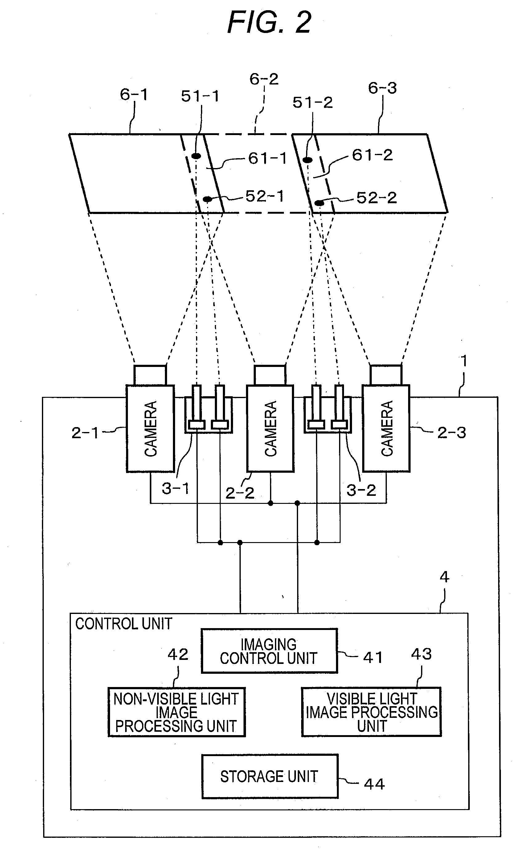
[0040]A plural camera images capturing and processing apparatus according to a first embodiment includes an imaging means corresponding to visible light with a first wavelength and non-visible light with a second wavelength and a marker giving means which gives a marker of the non-visible light with the second wavelength.

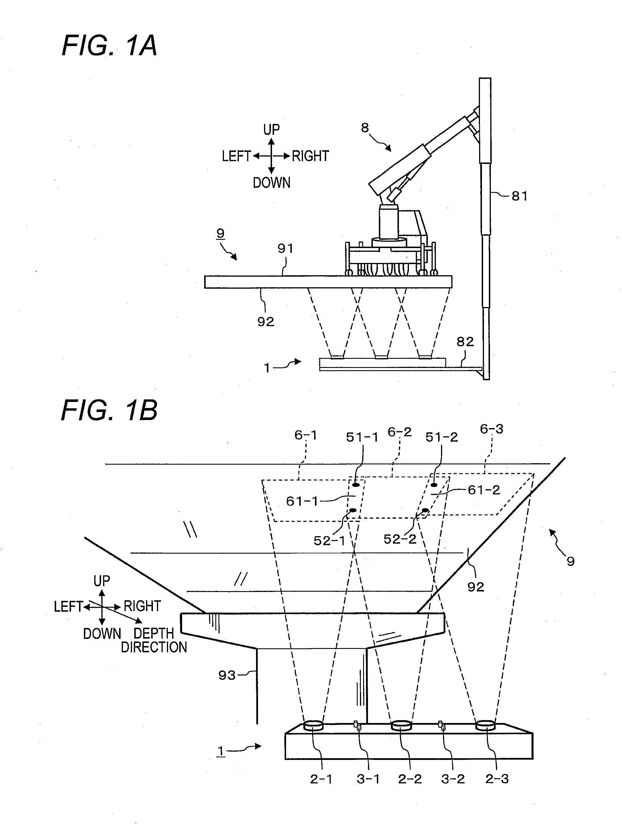
[0041]FIGS. 1A and 1B are diagrams illustrating the outward appearance and operation of a plural camera images capturing and processing apparatus 1 according to the first embodiment.

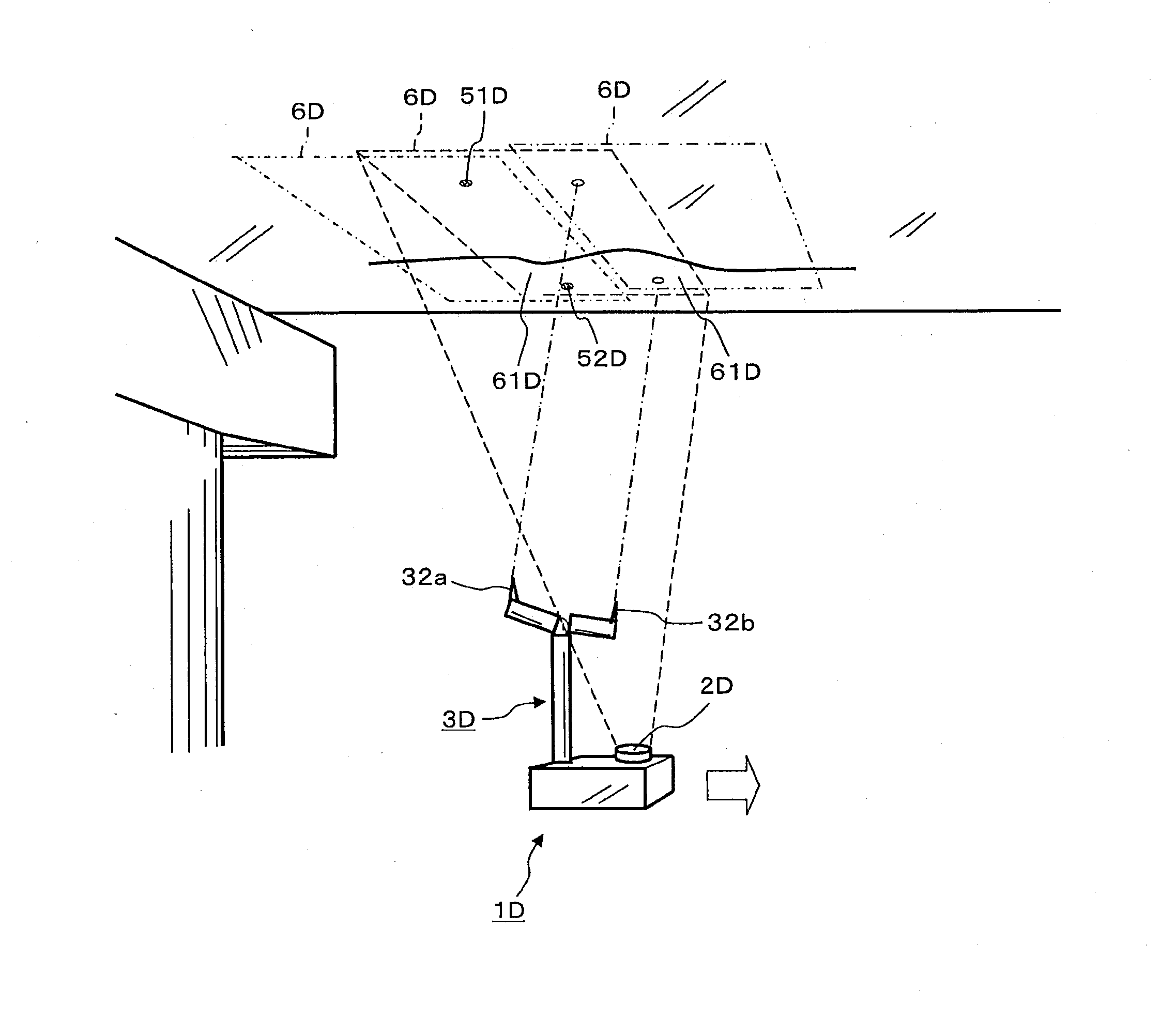
[0042]FIG. 1A is a diagram illustrating the outward appearance of a concrete bridge 9 which is an object to be captured, the plural camera images capturing and processing apparatus 1, and a bridge inspection vehicle 8 which supports the plural camera images capturing and processing apparatus 1.

[0043]A road 91 on which, for example, the bridge inspection vehicle 8 travels is on the concrete bridge 9. A lower surface 92 of the concrete bridge 9 is an object to be captured in this embodimen...

second embodiment

[0113]FIGS. 7A and 7B are diagrams illustrating the structure and operation of each camera 2A according to a second embodiment.

[0114]FIG. 7A is a diagram illustrating the structure of the camera 2A.

[0115]The camera 2A according to the second embodiment includes a dichroic prism 25, a visible light imaging element 26, and a non-visible light imaging element 27 in addition to the structure of the camera 2 according to the first embodiment.

[0116]The camera 2A a lens optical system 21 which focuses incident light to form an image, the dichroic prism 25 which separates the incident light into visible light and infrared rays, the visible light imaging element 26 which converts a visible light image into an electric signal, a visible light image processing unit 23 which generates a visible light image 71 from the electric signal converted by the visible light imaging element 26, the non-visible light imaging element 27 which converts an infrared image into an electric signal, and a non-vis...

third embodiment

[0123]In this embodiment, an example of a plural camera images capturing and processing apparatus 1B for observing, for example, cracks in a lower surface 92 of a concrete bridge 9 will be described. In this embodiment, the plural camera images capturing and processing apparatus 1B is stopped during an imaging operation and is moved along the lower surface 92 after the imaging operation.

[0124]FIG. 8 is a diagram schematically illustrating the structure of the plural camera images capturing and processing apparatus 1B according to the third embodiment.

[0125]The plural camera images capturing and processing apparatus 1B includes cameras 2B-1 to 2B-3 for visible light which are different from those in the first embodiment, laser devices 3B-1 and 3B-2 which are different from those in the first embodiment and radiate visible laser beams, and a control unit 4B which is connected to the cameras 2B-1 to 2B-3 and the laser devices 3B-1 and 3B-2. The laser device 3B-1 radiates visible laser ...


PUM

PropertyMeasurementUnit
wavelengthaaaaaaaaaa
second wavelengthaaaaaaaaaa
specific wavelengthaaaaaaaaaa

Abstract

A plural camera images capturing and processing apparatus includes a plurality of cameras that capture images of a plurality of adjacent imaging regions which overlap each other, a plurality of laser devices that give a marker to each common imaging region in which imaging regions overlap each other, an imaging control unit that controls each camera and each laser device and acquires a markerless image group to which no marker is given and a marker-given image group to which the marker is given, a non-visible light image processing unit that calculates a correction parameter, which is information for aligning the inclinations, sizes, and positions of the imaging regions, on the basis of the marker-given image group, and a visible light image processing unit that composes the markerless image group to generate a composite image, on the basis of the correction parameter.

Description

CROSS-REFERENCE TO RELATED APPLICATION[0001]This application claims the priority of Japanese Patent Application No. 2013-032713 filed Feb. 22, 2013, which is incorporated herein by reference in its entirety.BACKGROUND OF THE INVENTION[0002]1. Field of the Invention[0003]The present invention relates to a plural camera images capturing and processing apparatus and a composite imaging method which capture an image of a wide area with high resolution.[0004]2. Description of the Related Art[0005]In recent years, structures, such as bridges or tunnels which have been constructed during the high-growth period, have started to reach their expected lifetime. Therefore, there is an increasing demand for inspecting the damaged state of the structures and determining the necessity for restoring or repairing the structures. In the technique according to the related art which inspects the damaged state of the structures, when it is difficult for an inspector to inspect the structure on the road,...

Claims


Application Information

Patent Timeline
Patent Type & Authority Applications(United States)
IPC IPC(8): G01N21/88H04N5/232
CPCG01N21/8806H04N5/23238G06T3/4038H04N23/698H04N23/90
Inventor SAKANO, SHINJINONAKA, YUICHI
Owner HITACHI LTD
Why Eureka
Try Eureka