
Method and apparatus for gain and level correction of multi-tap ccd cameras

a multi-tap ccd camera and gain level technology, applied in the direction of television system, solid-state device signal generator, picture signal generator, etc., can solve the problems of pvt (process, voltage, and/or temperature), differences in the gain and/or black level of each group of individually read out pixels, and inherent response errors of multi-tap ccd cameras

Active Publication Date: 2014-08-28
RAYTHEON CO
View PDF4 Cites 3 Cited by
  • Summary
  • Abstract
  • Description
  • Claims
  • Application Information

AI Technical Summary

Benefits of technology

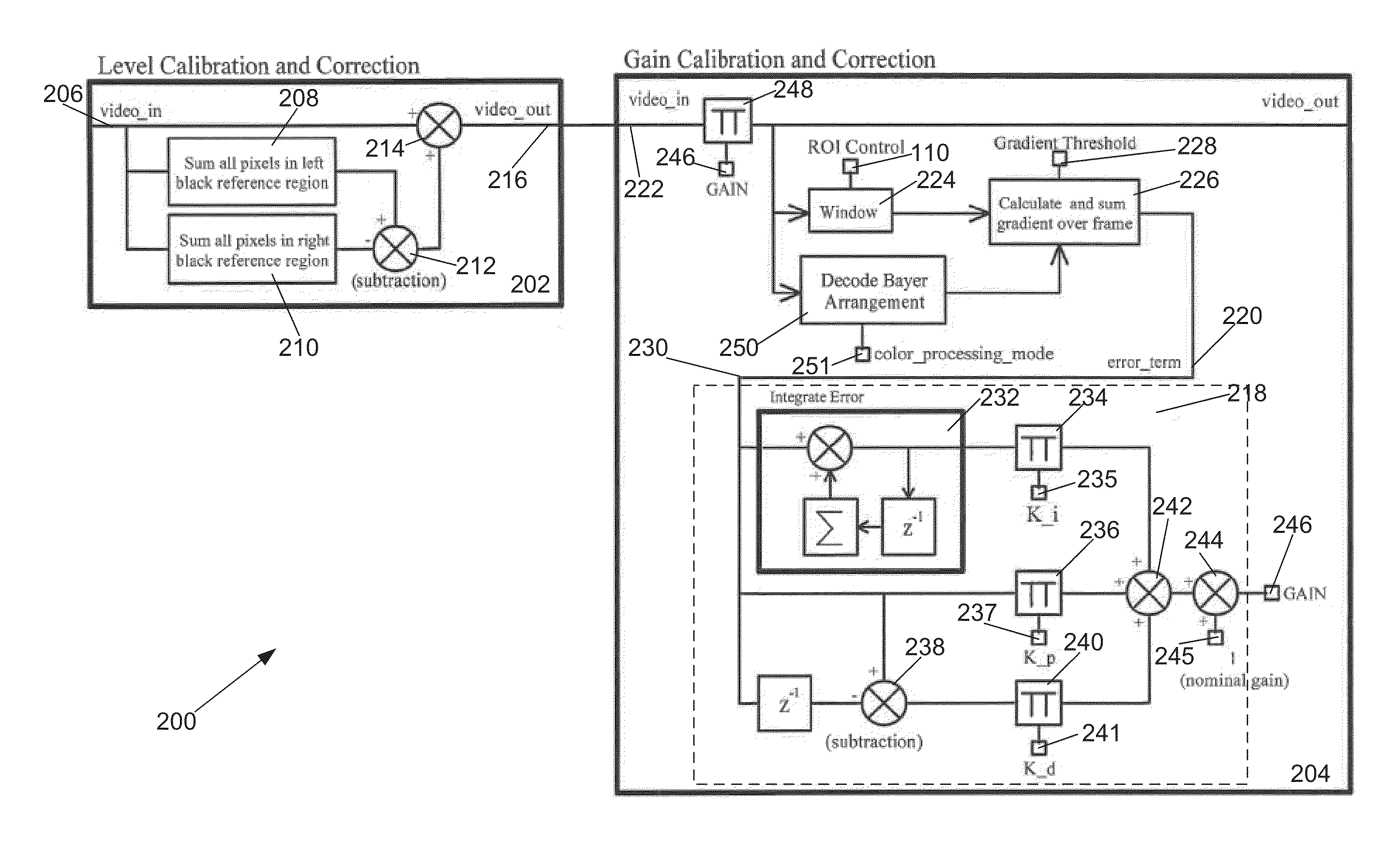
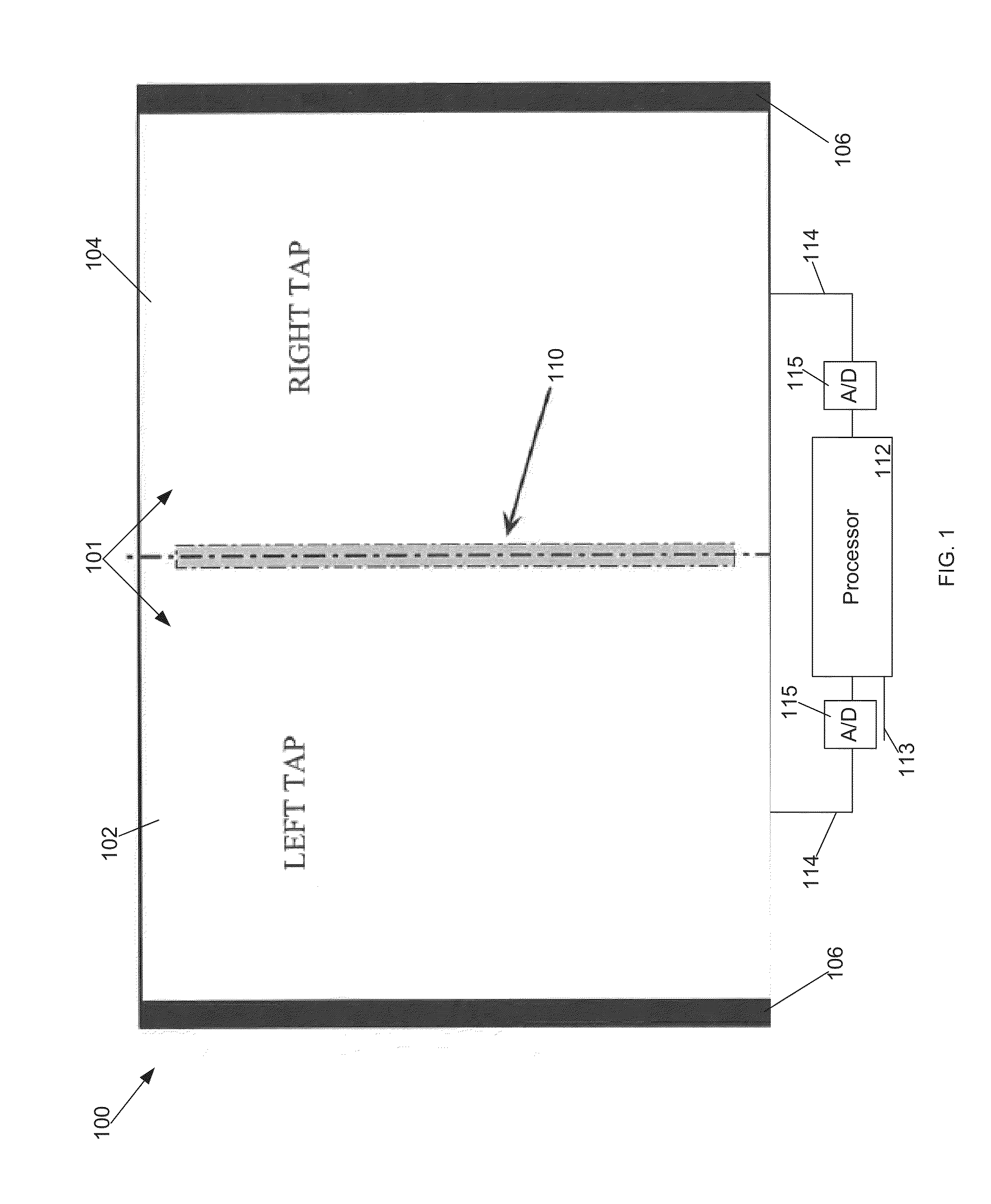
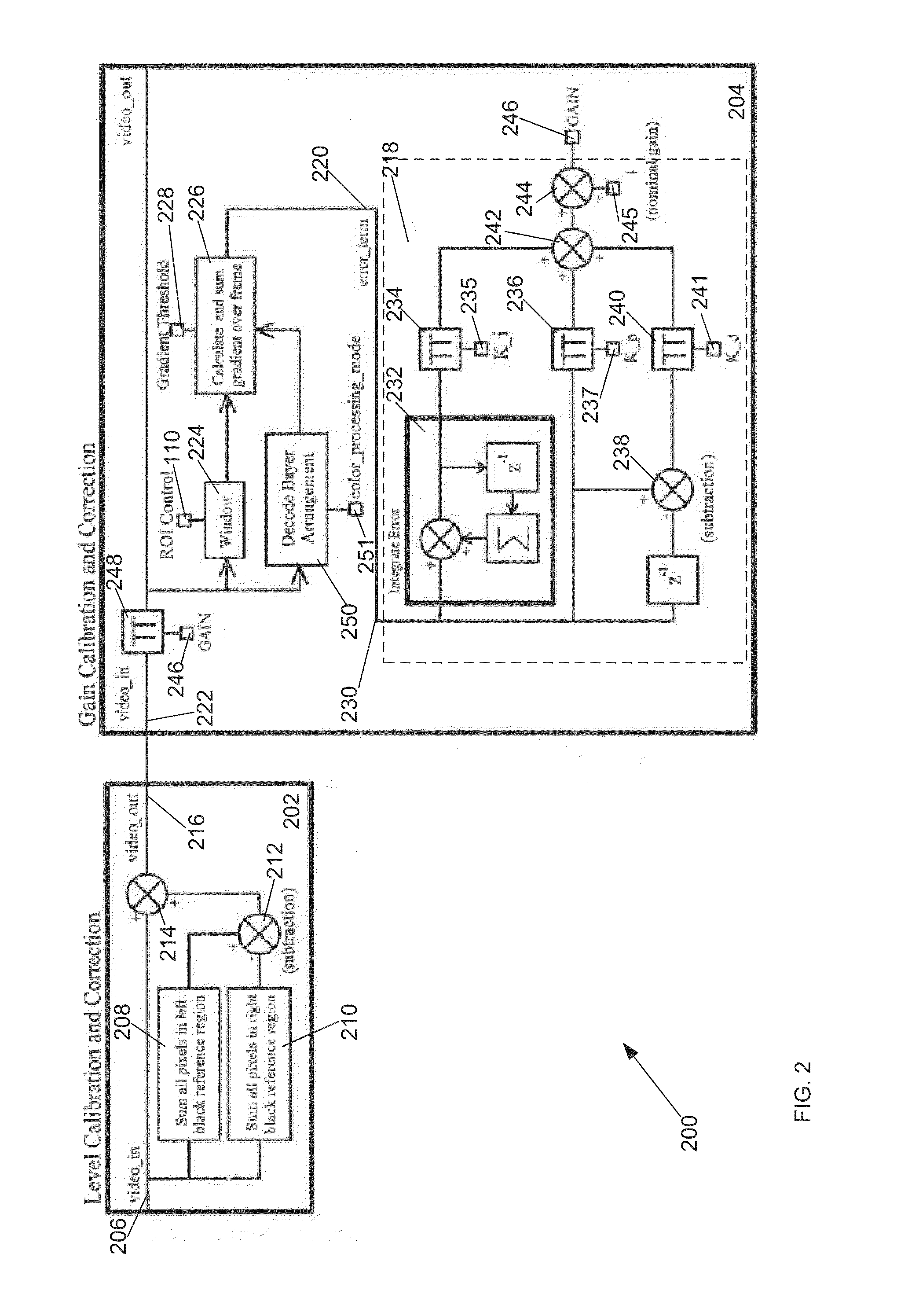
The patent discusses a method for accurately matching the gain of a camera with changes in the scene being imaged. This is achieved by measuring gradients at specific points in the scene and using those gradients to calculate a gain correction term. The method also filters out scene-based gradients that may affect the gain error. Additionally, the method selectively enables gain correction only when there is significant motion in the scene. The resulting method achieves tighter gain matching and higher resolution than conventional methods, without requiring a mask or shroud to perform black level correction. The patent also describes a CCD camera that includes a pixel array with two segments and a processor to combine the signals from both segments while reducing level and gain errors between them.

Problems solved by technology

These multi-tap CCD cameras exhibit inherent response errors between the readouts of the different paths.
For example, PVT (process, voltage, and / or temperature) variations in each path may produce errors.
As a result, there may be differences in the gain and / or black levels of each group of individually read out pixels from each path.
As a result of poor tap / channel matching between paths of the multi-tap CCD camera, the difference in the pixels read out from each path may result in a “split screen” visual effect when the pixels from each path are combined into a single image.
Digital image processing also typically performs contrast-enhancing and / or peaking operations on the image frame which may increase the error(s) between pixels from each path.
In this method, gain resolution is limited by the control resolution and PVT variance of the analog to digital converter, and as a result, the minimum gain error is at least several digital counts.

Method used


Image

  • Method and apparatus for gain and level correction of multi-tap ccd cameras
  • Method and apparatus for gain and level correction of multi-tap ccd cameras
  • Method and apparatus for gain and level correction of multi-tap ccd cameras

Examples


Embodiment Construction

[0028]As described above, poor tap / channel matching between paths of a multi-tap CCD sensor may result in a “split screen” visual effect in a resulting image generated by the multi-tap CCD sensor. As also discussed above, prior attempts so address this problem have resulted in solutions with gain errors of at least several digital counts. Accordingly, aspects and embodiments described herein provide methods and apparatus for reducing level (offset) and gain error between readouts of a multi-readout (or multi-tap) CCD sensor to one digital count or less.

[0029]It is to be appreciated that embodiments of the methods and apparatuses discussed herein are not limited in application to the details of construction and the arrangement of components set forth in the following description or illustrated in the accompanying drawings. The methods and apparatuses are capable of implementation in other embodiments and of being practiced or of being carried out in various ways. Examples of specific...


PUM


Abstract

According to one aspect, embodiments herein provide a CCD sensor comprising a pixel array having a first segment configured to produce a first tap signal responsive to receipt of electromagnetic radiation from a scene to be imaged, a second segment configured to produce a second tap signal responsive to receipt of the electromagnetic radiation from the scene, a region of interest including a portion of the first segment adjacent the second segment and a portion of the second segment adjacent the first segment, and a processor configured to receive the first and second tap signals, perform level correction on one of the first and second tap signals based on magnitudes of the first and second tap signals, and perform gain correction on one of the first and second tap signals based on a comparison between magnitudes of the first and second tap signals corresponding to the region of interest.

Description

CROSS-REFERENCE TO RELATED APPLICATIONS[0001]This application claims priority under 35 U.S.C. §119(e) to U.S. Provisional Application No. 61 / 770,505, entitled “METHOD AND APPARATUS FOR GAIN AND LEVEL CORRECTION OF BAYER COLOR MULTI-TAP CCD CAMERAS,” filed Feb. 28, 2013, which is hereby incorporated by reference in its entirety for all purposes.FEDERALLY SPONSORED RESEARCH[0002]This invention was made with U.S. government support under a grant awarded by the Department of Defense (Grant No. Withheld). The U.S. government has certain rights in this invention.BACKGROUND[0003]Charge coupled device (CCD) cameras are commonly used in digital imaging systems. Multi-tap CCD cameras split an image frame into two or more areas that are read out from the CDD camera in parallel. For example, an image frame of a multi-tap CCD camera may be divided into left and right halves, and the pixels in each half are read out from each half in parallel electrical paths. These multi-tap CCD cameras exhibit ...

Claims


Application Information

Patent Timeline
IPC IPC(8): H04N5/351H04N9/04H04N5/372
CPCH04N5/351H04N5/37213H04N9/045H04N23/6812H04N23/76H04N25/672H04N25/673H04N25/63
Inventor JACOBS, TRENT
Owner RAYTHEON CO
Learn More