Color filter and display apparatus including the same
- Summary
- Abstract
- Description
- Claims
- Application Information
AI Technical Summary
Benefits of technology
Problems solved by technology
Method used
Image

Examples
example 1
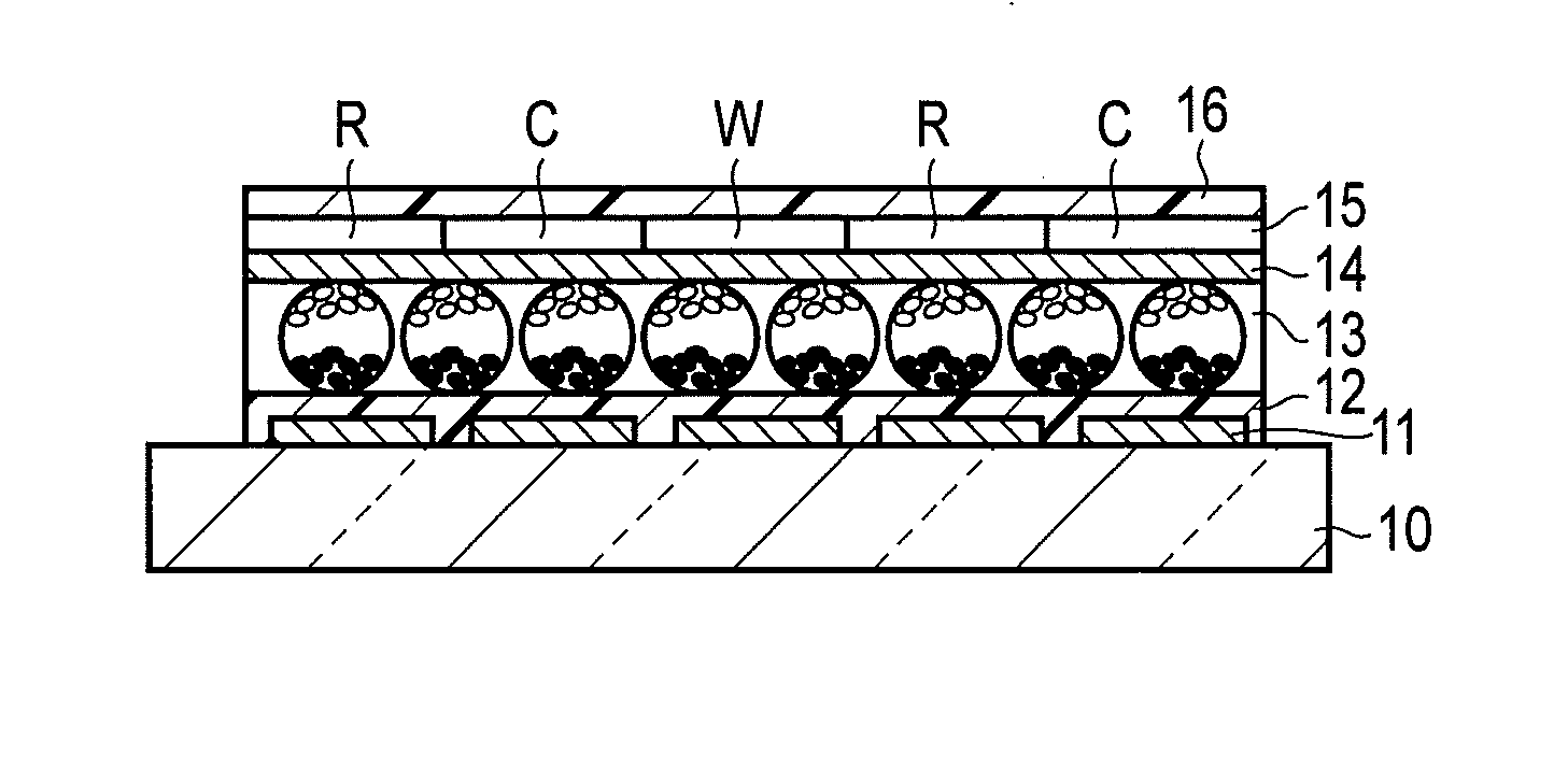
[0058]An electrophoretic display apparatus having the structure illustrated in FIG. 1 was prepared.
[0059]A dispersion liquid was obtained by dispersing titanium oxide powder (white particles) having an average grain size of 3 μm and each having a surface coated with polyethylene resin and carbon black powder (black particles) having an average grain size of 4 μm and having been subjected to surface treatment with alkyltrimethyl ammonium chloride in tetrachloroethylene. In this case, the white particles were negatively charged, and the black particles were positively charged.
[0060]The dispersion liquid was emulsified into an oil-in-water type emulsion, microcapsules were formed by complex-coacervation with gelatin and gum arabic, and thereby the dispersion liquid was encapsulated into microcapsules. The microcapsules obtained as described above were subjected to sieving to make the grain size uniform, such that the microcapsules had an average grain size of 60 μm and the ratio of mic...
example 2
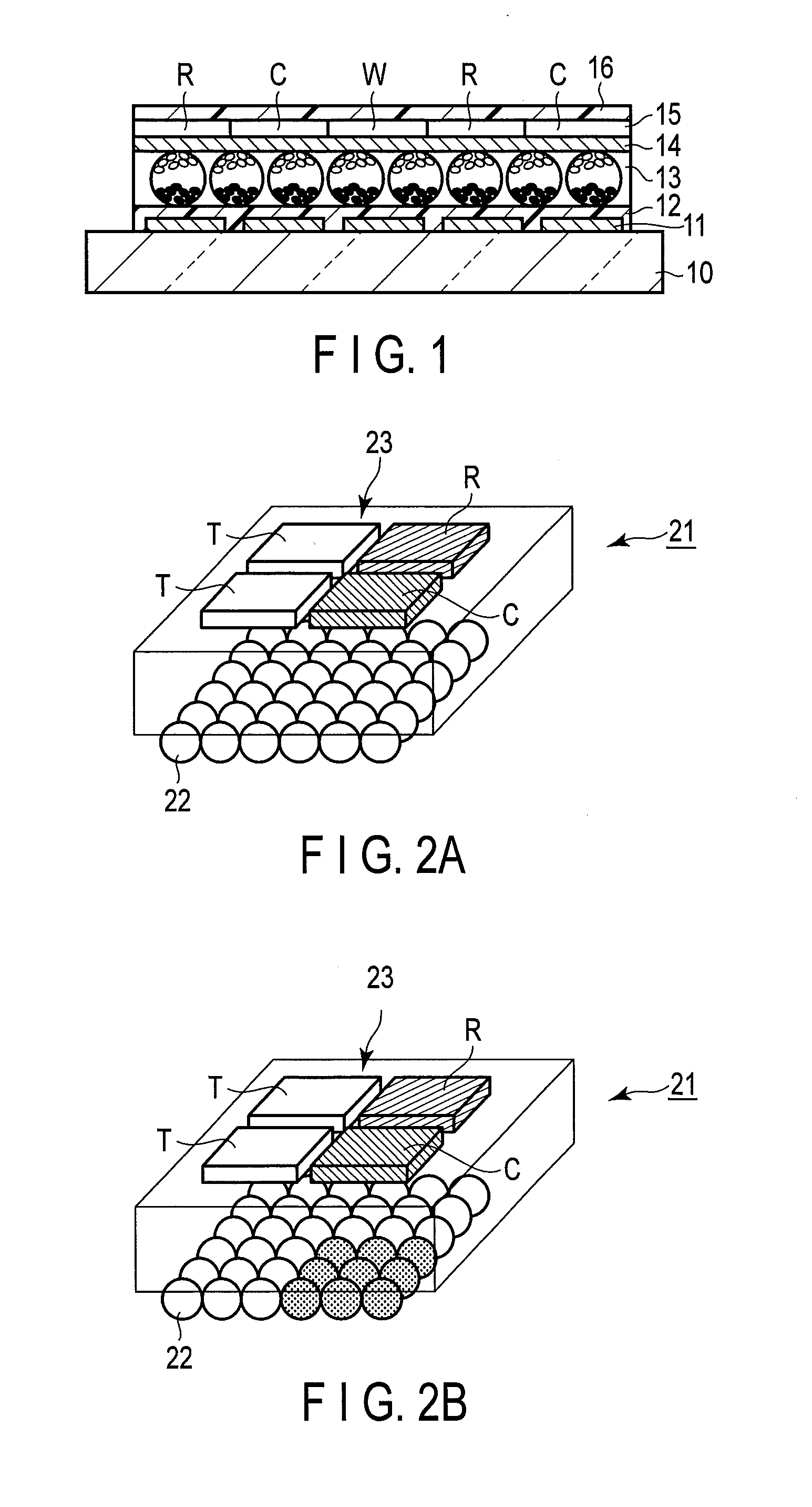
[0068]An electrophoretic display apparatus was finished in the same manner as Example 1, except that each pixel in Example 1 was made by diagonally arranging a rectangular blue subsidiary pixel, a rectangular yellow subsidiary pixel, and two rectangular transparent subsidiary pixels.
[0069]The reflectivity and values “a*” and “b*” of the display surface of the electrophoretic display apparatus prepared as described above were measured in the same manner as Example 1.
[0070]As a result, the reflectivity in white display was 30.1%, and the reflectivity in blue display when only the part of the electrophoretic display layer corresponding to the yellow subsidiary pixel was set to black was 16.1%. Both the reflectivities exhibited high values.
[0071]The value “a*” in white display was −4.3, the value “b*” was −1.2, and thus clear white display was obtained.
example 3
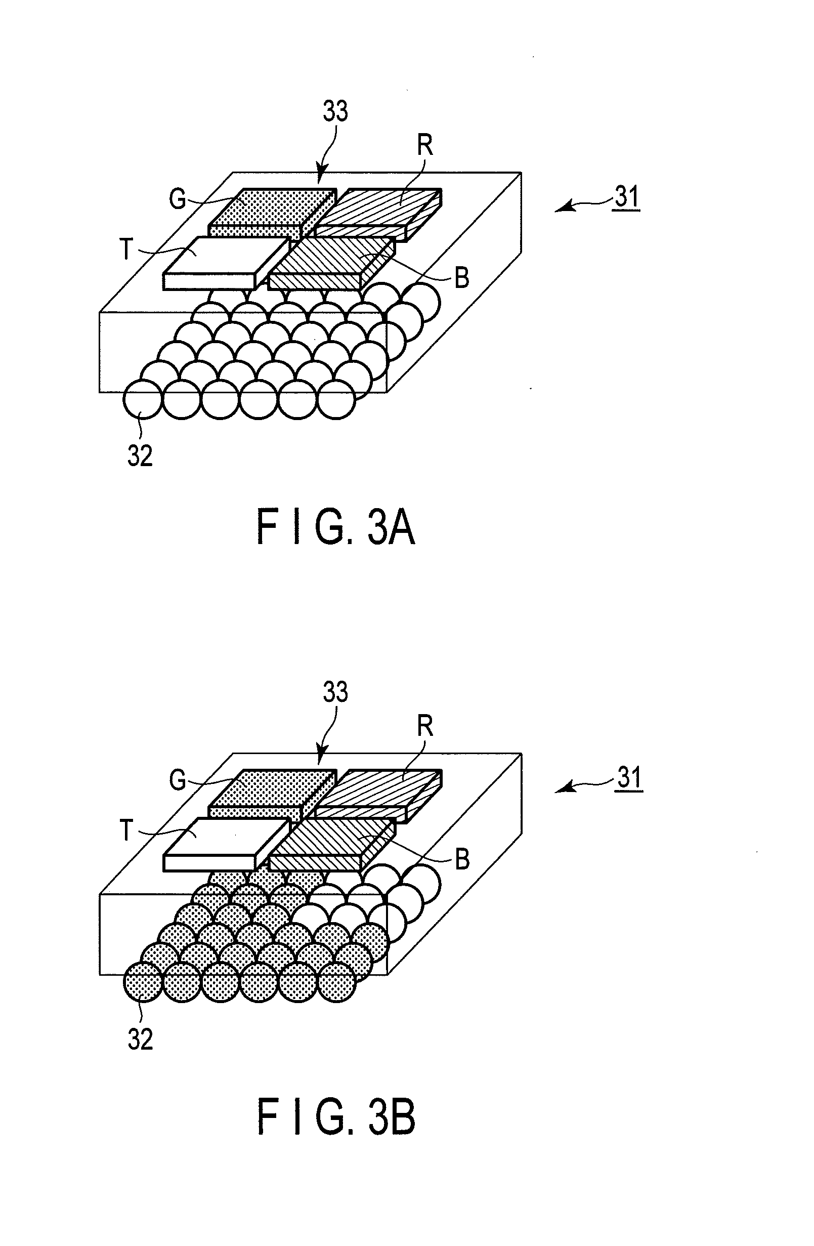
[0072]An electrophoretic display apparatus was finished in the same manner as Example 1, except that each pixel in Example 1 was made by diagonally arranging a rectangular green subsidiary pixel, a rectangular magenta subsidiary pixel, and two rectangular transparent subsidiary pixels.
[0073]The reflectivity and values “a*” and “b*” of the display surface of the electrophoretic display apparatus prepared as described above were measured in the same manner as Example 1.
[0074]As a result, the reflectivity in white display was 31.5%, and the reflectivity in green display when only the part of the electrophoretic display layer corresponding to the magenta subsidiary pixel was set to black was 18.2%. Both the reflectivities exhibited high value.
[0075]The value “a*” in white display was −4.4, the value “b*” was −1.0, and thus clear white display was obtained.
PUM
 Abstract
Description
Claims
Application Information
 - R&D Engineer
- R&D Manager
- IP Professional
- Industry Leading Data Capabilities
- Powerful AI technology
- Patent DNA Extraction
Browse by: Latest US Patents, China's latest patents, Technical Efficacy Thesaurus, Application Domain, Technology Topic.
© 2024 PatSnap. All rights reserved.Legal|Privacy policy|Modern Slavery Act Transparency Statement|Sitemap