Matrix Ring for Tooth Restoration

a matrix ring and tooth technology, applied in the field of matrix rings, can solve the problem of insufficient tooth structure remaining to support the filling material, and achieve the effect of reducing the number of teeth and reducing the number of tooth cavities

Active Publication Date: 2014-08-28
GARRISON DENTAL SOLUTIONS
View PDF0 Cites 9 Cited by
  • Summary
  • Abstract
  • Description
  • Claims
  • Application Information

AI Technical Summary

Benefits of technology

[0008]At least one of the tines, and preferably both of the opposing tines having a frame body and a superimposed pad. The frame body includes a front defined by a central ridge, a first lower extension extending from a first side of the central ridge, and a second lower extension extending from a second side of the central ridge. The first lower extension has a top surface and a bottom surface terminating at an exposed face. The top surface and bottom surface cooperate to define a thickness that reduces toward the exposed face. A portion of the first lower extension proximate the exposed face is configured to rotate and translate relative to the re

Problems solved by technology

Typically, when tooth decay occurs near the outer edges of a tooth, there is often insuffi

Method used


Image

  • Matrix Ring for Tooth Restoration
  • Matrix Ring for Tooth Restoration
  • Matrix Ring for Tooth Restoration

Examples


Embodiment Construction

[0034]While this invention is susceptible of embodiment in many different forms, there is shown in the drawings and described herein in detail a specific embodiment with the understanding that the present disclosure is to be considered as an exemplification and is not intended to be limited to the embodiment illustrated.

[0035]It will be understood that like or analogous elements and / or components, referred to herein, may be identified throughout the drawings by like reference characters. In addition, it will be understood that the drawings are merely schematic representations of the invention, and some of the components may have been distorted from actual scale for purposes of pictorial clarity.

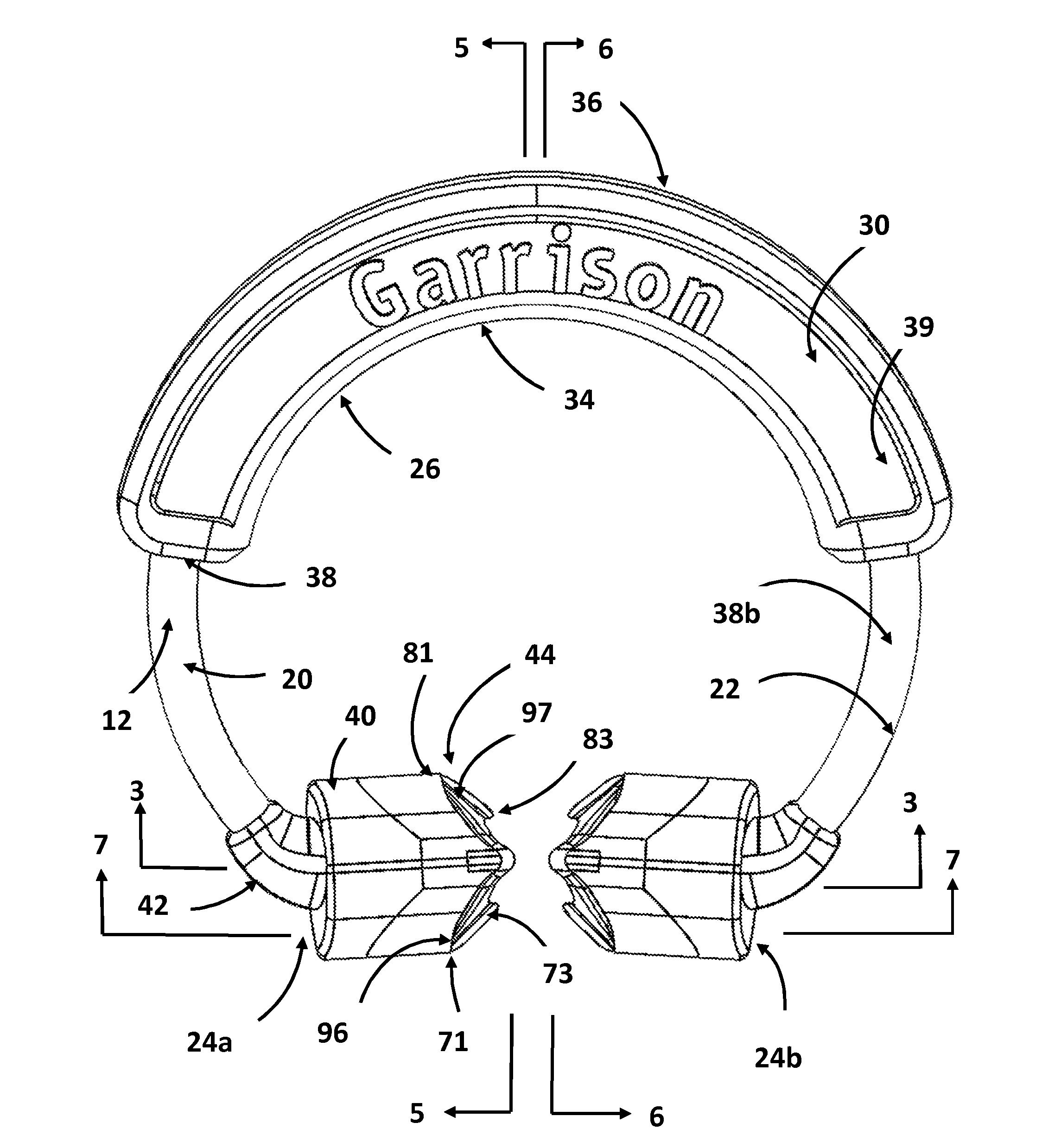
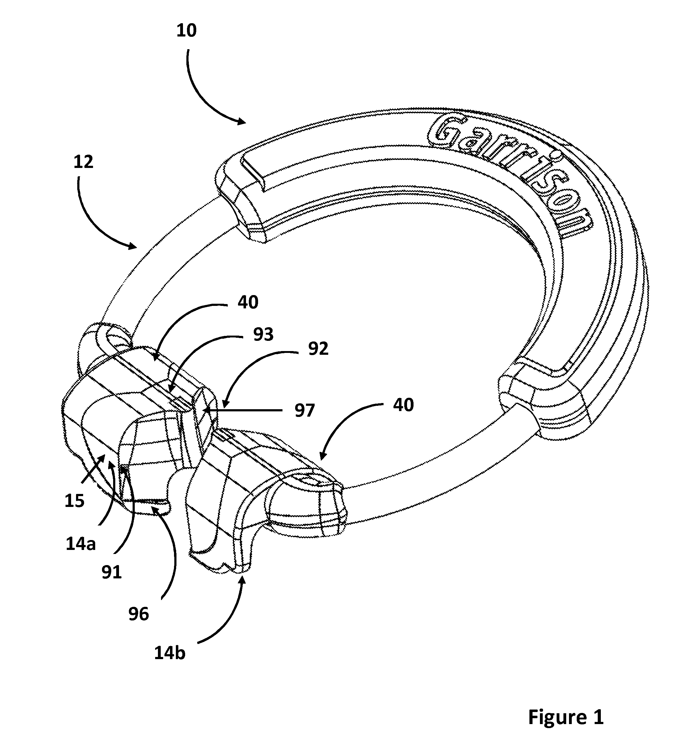
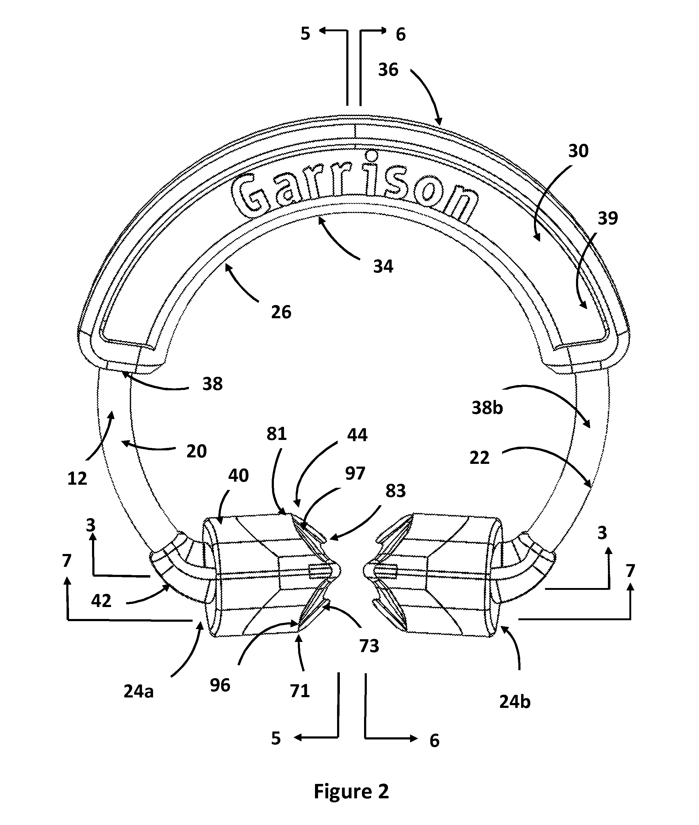
[0036]Referring now to the drawings and in particular to FIG. 1, the dental implement, or matrix ring, is shown generally at 10. The matrix ring 10 includes biasing ring 12 and opposing tines 14a, 14b. The dental implement is typically configured for separating adjoining teeth and for retaini...


PUM


Abstract

A matrix ring comprising includes a biasing ring and a pair of opposing tines. The biasing ring includes a substantially hoop-like configuration terminating at two opposing ends. The pair of opposing tines extend inwardly from each of the two ends of the biasing ring toward each other. Each of the pair of opposing tines is coupled to the respective opposing end about a central region thereof and extends radially outwardly therefrom. Each tine includes a frame body having a central ridge and opposing lower extensions, the lower extensions terminating at an exposed face. The portion of the lower extensions proximate the exposed face being able to move relative to the rest of the frame body so as to better position on the teeth of a patient. A superimposed pad over portions of the frame body provides a deformable surface for engagement with the surface of the tooth of a patient.
In the Specification
The opposing tines 14a, 14b are shown in FIG. 1. The opposing tines in the preferred embodiment are substantial mirror images of each other about a vertical plane substantial positioned between the interproximal space of the opposing tines. As a result, the opposing tine 14a will be described with the understanding that the opposing tine 14b is a 20 substantial mirror image thereof. To the extent that any structures are identified on the opposing tine 14b with reference numbers, these structures are denoted with the same reference number as on the opposing tine 14a.

Description

BACKGROUND OF THE DISCLOSURE[0001]1. Field of the Disclosure[0002]The invention relates in general to dental implements, and more particularly, to a matrix ring which is used to separate teeth and to hold a matrix band in place around a tooth when a cavity in the tooth is to be filled or otherwise repaired or restored.[0003]2. Background Art[0004]The use of retaining devices for holding matrix bands is well known in the art. Typically, when tooth decay occurs near the outer edges of a tooth, there is often insufficient tooth structure remaining to support the filling material prior to hardening thereof. To overcome this problem, a thin band is positioned about the tooth and secured to the tooth to provide the required support for the filling material. In such a manner, the filling material can be positioned as desired, and can be formed into the desired shape.[0005]To achieve the proper final desired shape, it is often necessary to separate the affected tooth from the immediately ad...

Claims


Application Information

Patent Timeline
IPC IPC(8): A61C5/12
CPCA61C5/125A61C5/82
Inventor ANDERSON, ROBERTDOENGES, SCOTTHULL, ALEX
Owner GARRISON DENTAL SOLUTIONS
Why Eureka
Try Eureka