Sand separator

a technology of sand separator and separator shaft, which is applied in the direction of separation process, vortex flow apparatus, and wellbore/well accessories, etc., can solve the problems of affecting the recovery of natural gas, creating additional challenges that must be dealt with, and affecting the operation of surface equipment and pipelines

Active Publication Date: 2014-08-28
2468042 ALBERTA LTD
View PDF19 Cites 16 Cited by
  • Summary
  • Abstract
  • Description
  • Claims
  • Application Information

AI Technical Summary

Problems solved by technology

Recovering natural gas is often not as straightforward as it appears, as the gas may not readily flow from the reservoir into the well bore as a result of a variety of factors including formation characteristics and pressures.
Horizontal drilling and hydraulic fracturing are generally effective at increasing the recovery of hydrocarbons, however they also create additional challenges that must be dealt with.
This particulate is produced to the surface and can cause plugging and / or erosion of surface equipment and pipelines.
The inside of the vessel is formatted such that when a high pressure, high velocity production stream from a well flows into the vessel through the inlet port, it experiences a large drop in velocity, causing the natural gas to separate from the water and sand.
While past sand separators can be effective, they are often limited by a number of operational limitations in the field.
In particular, in the event that a sudden pulse in water / sand is encountered, in past designs, this may lead to either ineffective water / sand separation from the gas, clogging of the sand filters of the separator and / or damage to the sand filters.

Method used


Image

  • Sand separator
  • Sand separator
  • Sand separator

Examples


Embodiment Construction

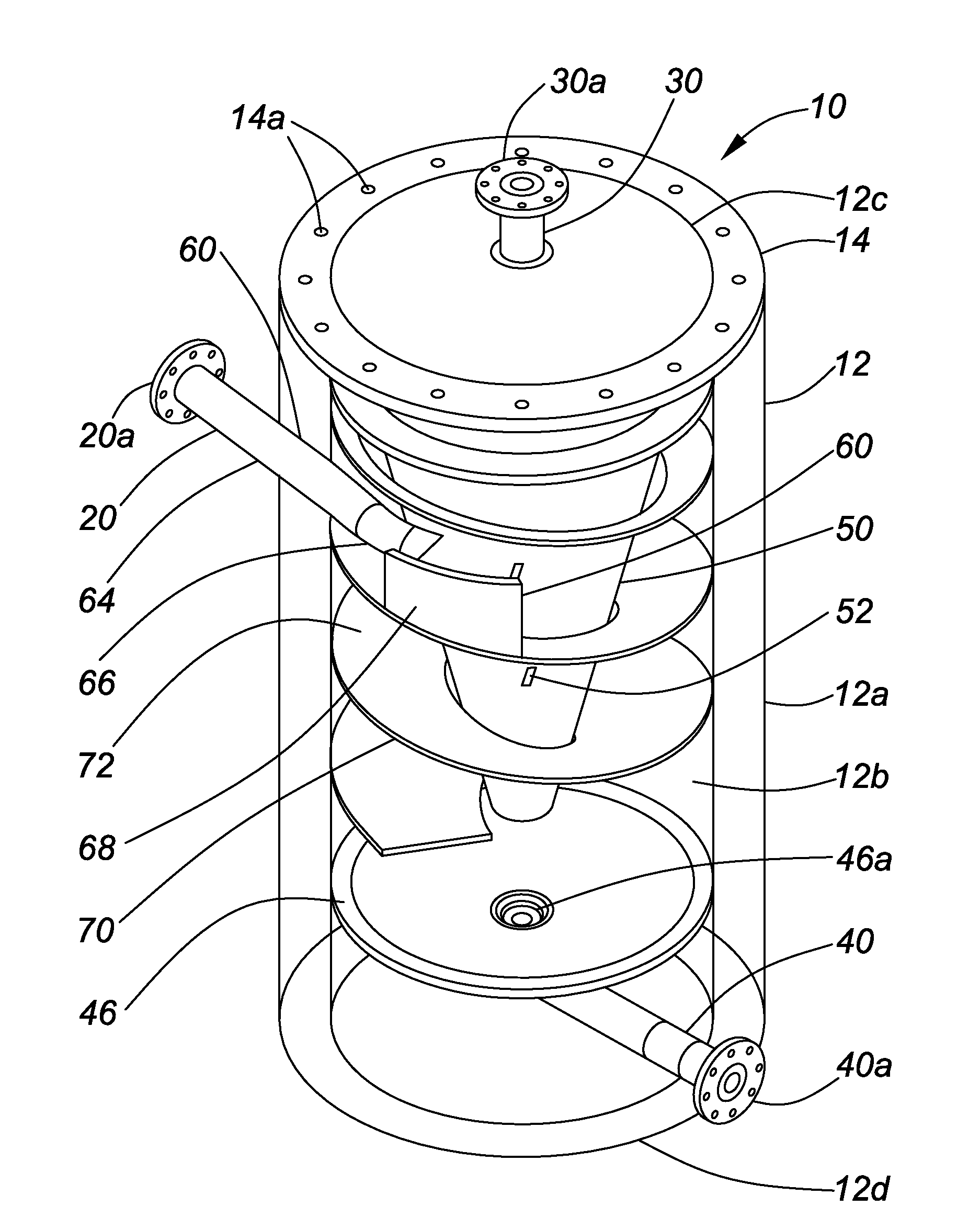
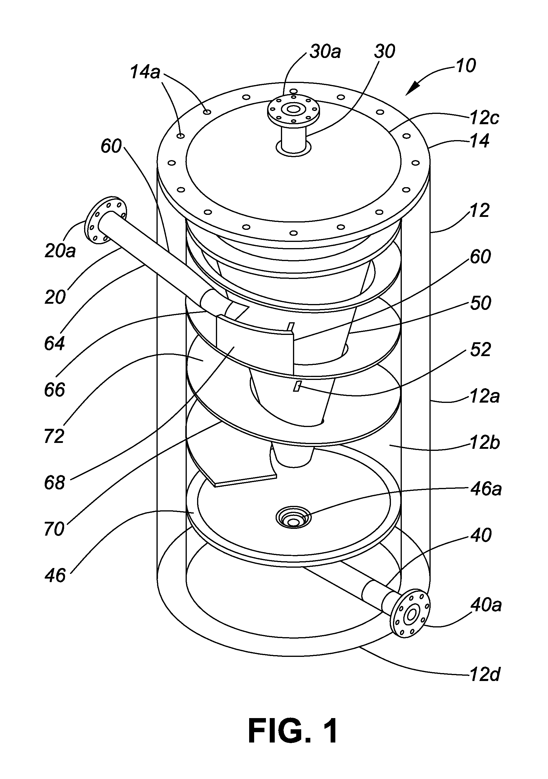
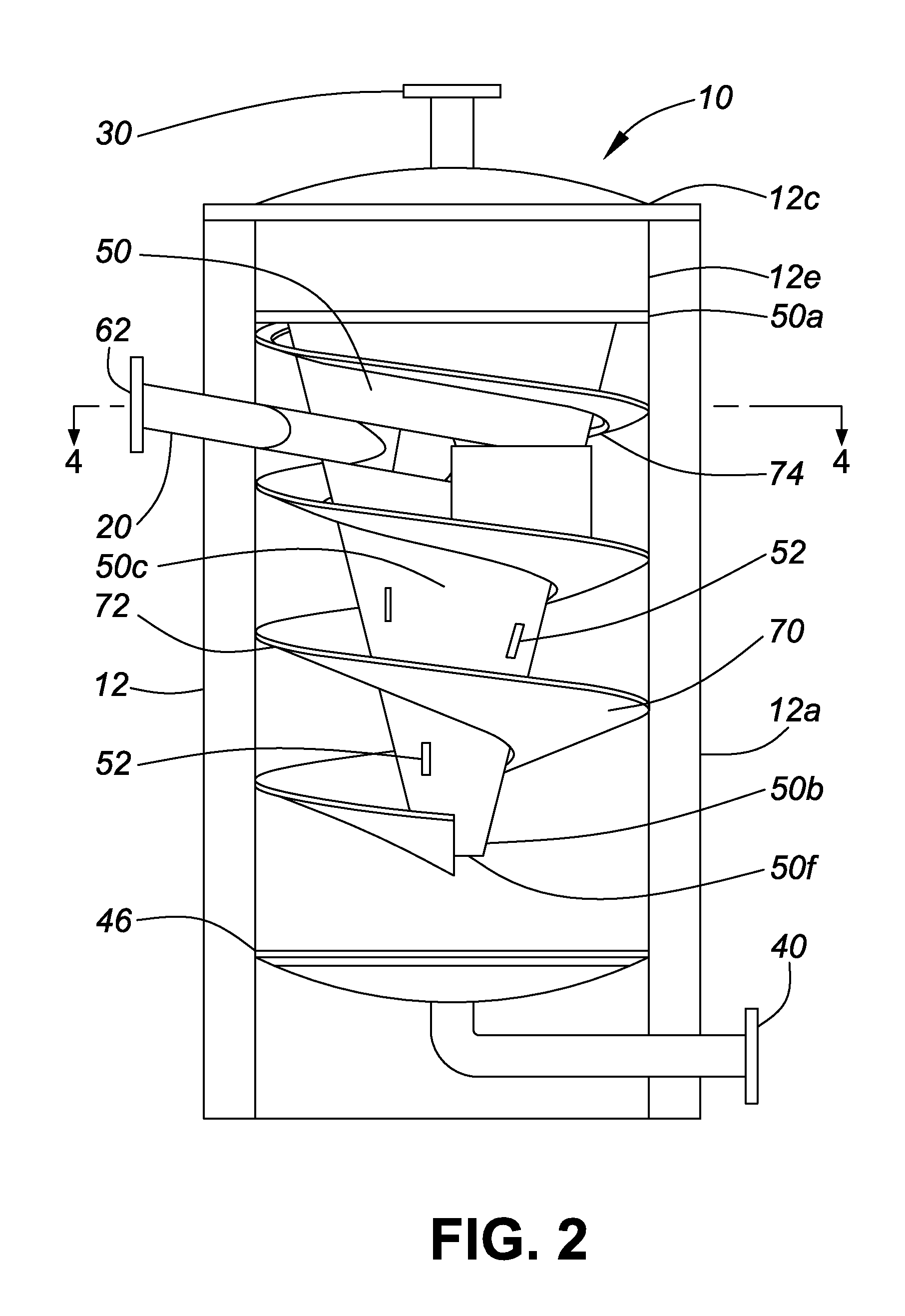
[0020]With reference to the figures, a sand separator 10 is described. The sand separator generally comprises a vessel 12 having an inlet pipe 20, a gas outlet pipe 30 and a drain 40. The interior of the sand separator comprises a collecting plate 46, an inner cone 50, a wear plate 60, and an auger 70. The sand separator is described herein with typical dimensions and as being manufactured from specific materials. It is understood, however, that variations in the dimensions and materials may be made while achieving the objectives of the invention as understood by those skilled in the art.

Vessel

[0021]Referring to FIGS. 1 and 2, the vessel 12 is preferably a cylindrical shaped hollow vessel having an outer wall 12a, inner cavity 12b, top end 12c, bottom end 12d. The external dimensions of the vessel are typically about 3 to 6 feet in diameter and 6 to 10 feet in height. The outer wall 12a, top end 12c and bottom end 12d of the vessel are fabricated from rolled steel and are of suffici...


PUM

PropertyMeasurementUnit
diameteraaaaaaaaaa
diameteraaaaaaaaaa
internal pressureaaaaaaaaaa

Abstract

An apparatus and method for separating a natural gas production stream from hydrocarbon well operations into a gas component and a sand and liquid component is described. More specifically, a sand separator comprising a cylindrical body, a production stream inlet port, a gas outlet port and a solid and liquid drain port is described. The cylindrical body has an inner cavity with an inner cone having one-way gas vents and a stationary auger wrapped around the inner cone. The production stream inlet port includes a pipe having a curved tip that directs the production stream into the body and around the inner cone and stationary auger, causing the production stream to slow down and the components to separate.

Description

FIELD OF THE INVENTION[0001]The invention relates to an apparatus for separating sand from a natural gas production stream during hydrocarbon well operations. More specifically, the invention relates to a sand separator having an interior space comprising an inner cone with one-way gas vents, wherein when a production stream enters the interior space, the sand and liquid particles are separated from the gaseous particles.BACKGROUND OF THE INVENTION[0002]As is well known and by way of background, natural gas is a naturally occurring hydrocarbon gas mixture consisting primarily of methane, up to 20% other hydrocarbons as well as varying amounts of impurities such as carbon dioxide. Natural gas is widely used as an energy source and it is generally found in deep underground natural rock formations or associated with other hydrocarbon reservoirs. The underground rock formations or subsurface reservoirs of hydrocarbons typically consist of a porous layer, such as limestone and sand, over...

Claims


Application Information

Patent Timeline
Patent Type & Authority Applications(United States)
IPC IPC(8): B04C3/06
CPCB04C5/04B04C5/085B01D45/12B04C5/13B04C5/14B04C5/103E21B43/34E21B43/35
Inventor LYON, BRUCEMCINTOSH, GORDON
Owner 2468042 ALBERTA LTD
Why Eureka
Try Eureka