Vibration damping device

a vibration damping and damping device technology, applied in the direction of shock absorbers, machine supports, other domestic objects, etc., can solve the problems of reducing the service life of the load bearing, the risk of adverse effects on the performance of the load bearing or the ride comfort, and the lack of rigidity of the vibration damping device, so as to reduce the moment in the falling direction, improve the load bearing performance, and efficiently maintain the load bearing performance

Active Publication Date: 2014-09-04
SUMITOMO RIKO CO LTD
View PDF9 Cites 14 Cited by
  • Summary
  • Abstract
  • Description
  • Claims
  • Application Information

AI Technical Summary

Benefits of technology

[0026]According to the seventh aspect, stabilization of the fluid-filled vibration damping device at a load input in the axis-perpendicular direction and enhancement of the load bearing performance can be effectively achieved. This is because, in the fluid-filled vibration damping device, the second mounting member extends upward since the fluid chamber is formed on the upper side of the main rubber elastic body. Therefore, due to its structural reasons, not only that the mass center of the vibration damping device tends to be positioned in the upper portion but also the position of the load input to the second mounting member in the axis-perpendicular direction is separated upward away from the first mounting member. By applying the present invention to the fluid-filled vibration damping device described above, the positions of the mass center of gravity including that of the outer bracket and the load input to the second mounting member in the axis-perpendicular direction can be lowered.
[0027]According to the present invention, with the inverted-type vibration damping device, the bottom edge of the second mounting member and the top edge of the outer bracket are coupled to each other and the outer bracket protrudes downward from the second mounting member. Thus, the center of gravity of the vibration damping device can be set at a lower position, thus efficiently maintaining the load bearing performance in the falling direction. In addition, an axis-perpendicular stopper member where a load is inputted in the axis-perpendicular direction is provided in the lower portion of the vibration damping device to reduce the moment in the falling direction caused by the input of the stopper load. Therefore, the load bearing performance is maintained more favorably, thus achieving stable support of the vibration source as well as stability of the vibration damping performance.

Problems solved by technology

However, since a massive bracket is fixed by press-fitting to the second mounting member constituting the upper portion of the vibration damping device in the vibration damping device shown in JP-B-4755147, the center of gravity thereof is positioned in the upper portion, which posed a risk of developing problems such as lack of rigidity of the vibration damping device in the falling direction.
In addition, in the structure of JP-B-4755147, since an axis-perpendicular stopper member that restricts relative displacement between the first mounting member and the second mounting member in the axis-perpendicular direction (front-back direction of the vehicle) is provided on the upper portion of the vibration damping device, there were some problems such as further deviation upward of the center of gravity position and a risk of adverse effects on the load bearing performance or ride comfort caused by a stopper load of the axis-perpendicular stopper member acting on the upper portion of the vibration damping device during acceleration and deceleration of the motor vehicle.

Method used


Image

  • Vibration damping device
  • Vibration damping device
  • Vibration damping device

Examples


first embodiment

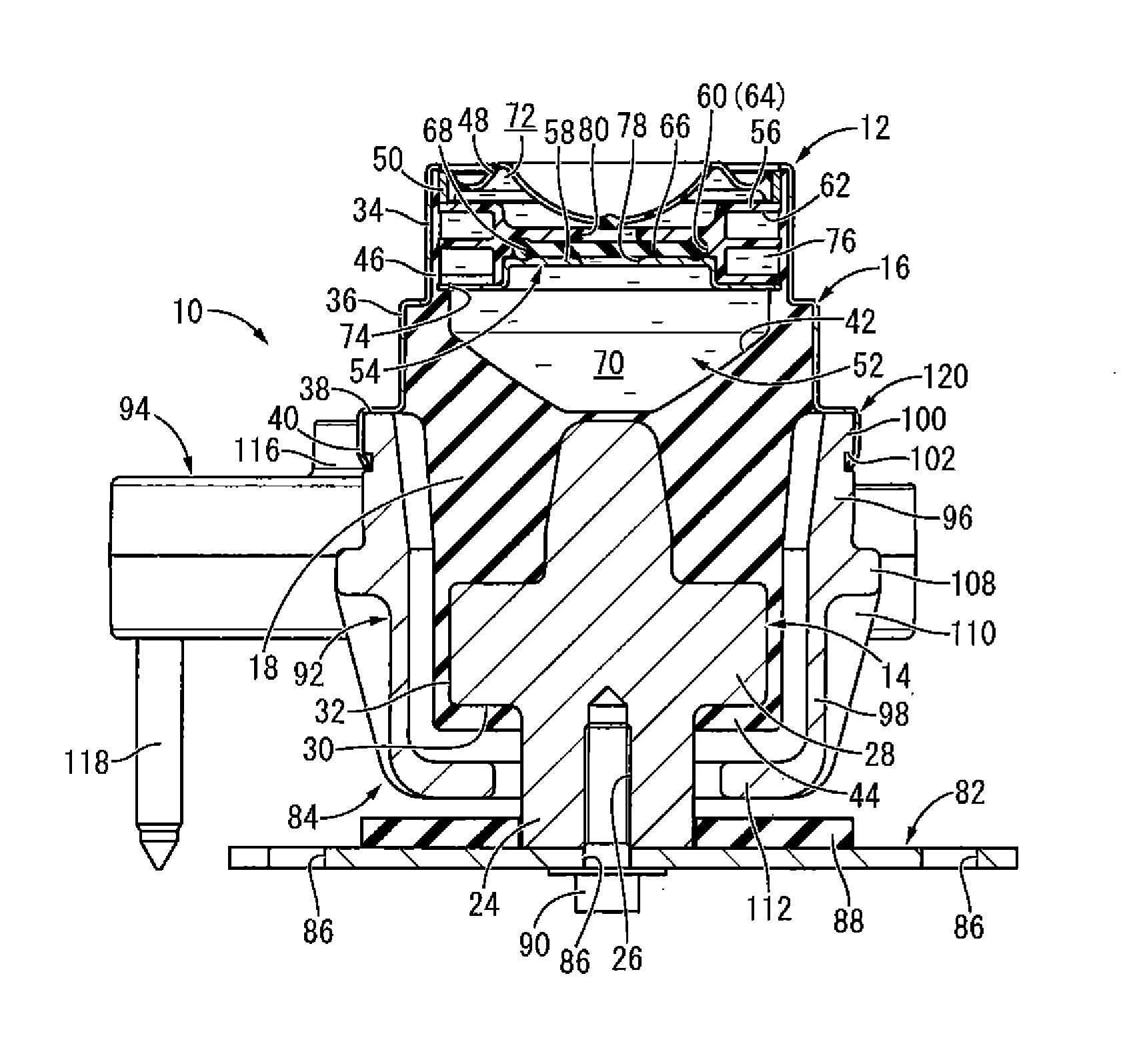
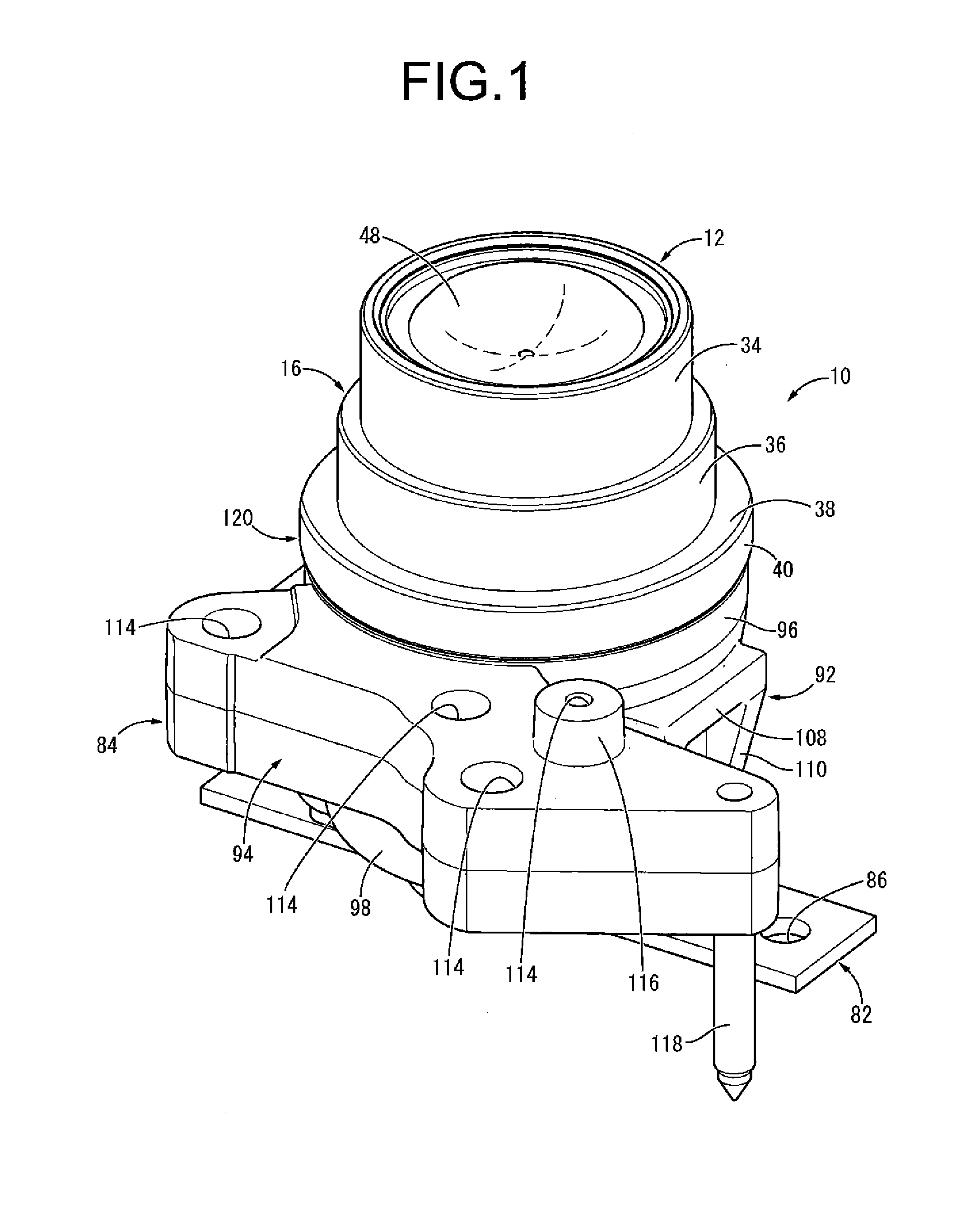
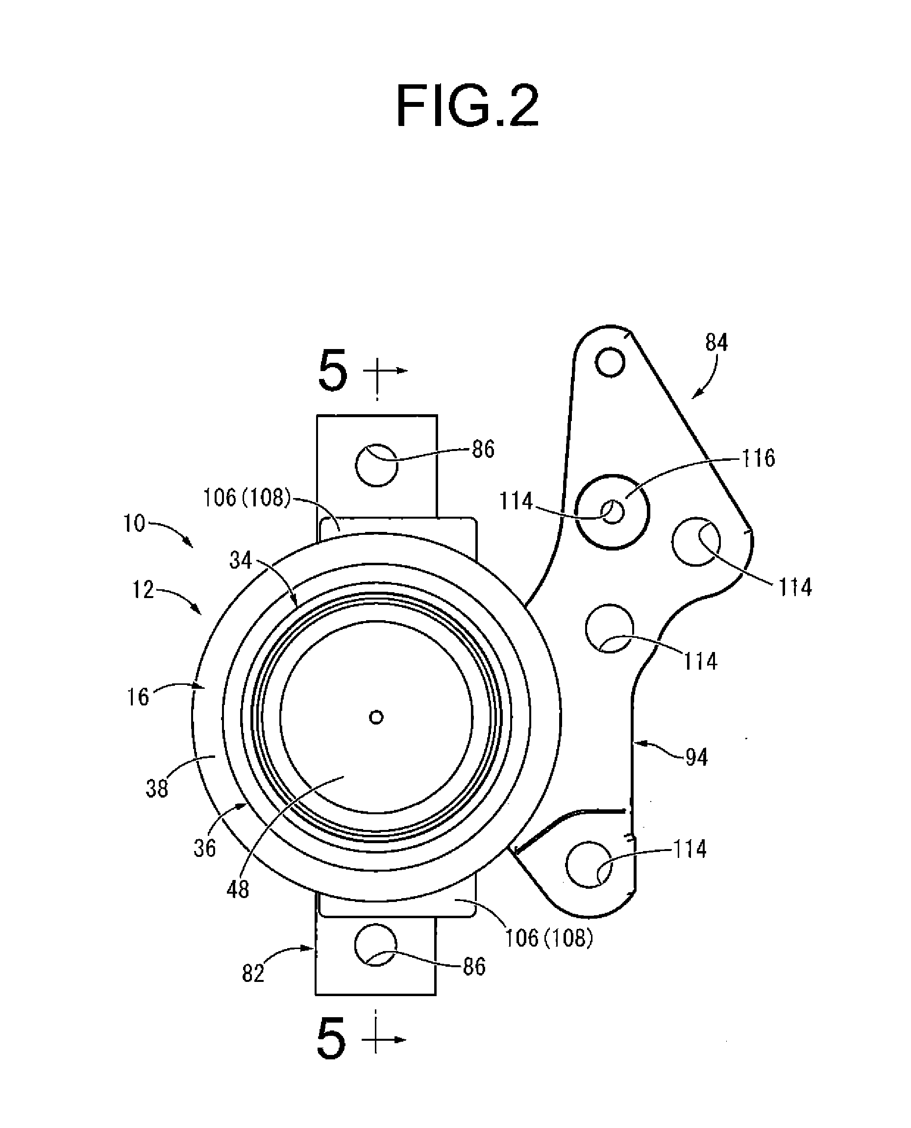
[0048]FIGS. 1 to 5 show an automotive engine mount 10 as the vibration damping device with the structure according to the present invention. The engine mount 10 is a fluid-filled vibration damping device comprising a mount main body 12, which has a structure where a first mounting member 14 and a second mounting member 16 are elastically connected by a main rubber elastic body 18. Then, the first mounting member 14 is attachable to a vehicular body 20 as a member to be vibration-damped, while the second mounting member 16 is to be attached to a power unit 22 as a vibration source. In the following descriptions, the “up-down direction” (or “vertical”) generally means the up-down direction in FIG. 5, which is the central axis direction of the mount. Also, under a condition where the engine mount 10 is mounted on a vehicle, the downward direction in FIG. 2 is the forward direction of the vehicle.

[0049]More specifically, the first mounting member 14 is a high-rigidity member formed with...

third embodiment

[0096]FIG. 16 shows an automotive engine mount 160 as the vibration damping device with the structure according to the present invention. The engine mount 160 has a structure where the inner bracket 82 and the outer bracket 84 are attached to a mount main body 162.

[0097]More specifically, the mount main body 162 has a structure where the first mounting member 14 and a second mounting member 164 are elastically connected by the main rubber elastic body 18, while the second mounting member 164 comprises an intermediate sleeve 166 and an outer cylindrical member 168.

[0098]The intermediate sleeve 166 is a high-rigidity member formed with a metal material and the like in an approximate shape of a large-diameter cylinder, on the lower side which is arranged the first mounting member 14 on the same central axis, and the first mounting member 14 and the intermediate sleeve 166 are elastically connected by the main rubber elastic body 18. The main rubber elastic body 18 of the present embodi...


PUM


Abstract

A vibration damping device including a first mounting member arranged on a lower side of a second mounting member, the first and second mounting members being elastically connected by a main rubber elastic body, and an outer bracket arranged on the lower side of the second mounting member. A coupling part is constituted by engagement between a bottom edge of the second mounting member and a top edge of the outer bracket, and the second mounting member is configured to be attached to a vibration source via the outer bracket. The outer bracket is arranged in opposition to the first mounting member in an axis-perpendicular direction, and an axis-perpendicular stopper member that regulates relative displacement between the first and second mounting members in the axis-perpendicular direction is constituted by contact between the first mounting member and the outer bracket.

Description

INCORPORATED BY REFERENCE[0001]The disclosure of Japanese Patent Application No. 2012-029525 filed on Feb. 14, 2012 including the specification, drawings and abstract is incorporated herein by reference in its entirety. This is a Continuation of International Application No. PCT / JP2012 / 007361 filed on Nov. 16, 2012.BACKGROUND OF THE INVENTION[0002]1. Field of the Invention[0003]The present invention relates to a vibration damping device to be used, for example, for engine mounts and the like on motor vehicles.[0004]2. Description of the Related Art[0005]Conventionally, there has been known a vibration damping device interposed between members constituting a vibration transmission system to link or support the members each other in a vibration damping manner, which has been considered for application to engine mounts and the like on motor vehicles. This vibration damping device, as shown in Japanese Unexamined Patent Publication No. JP-A-11-311291 and others, has a structure where a ...

Claims


Application Information

Patent Timeline
Patent Type & Authority Applications(United States)
IPC IPC(8): F16F15/02F16F13/08F16F15/08F16M13/02
CPCF16F15/022F16F15/08F16F13/08F16M13/02F16F13/1409F16F13/10F16F13/107F16F13/262
Inventor ICHIKAWA, HIROYUKIYASUDA, TAKAYOSHISAIKI, AKIO
Owner SUMITOMO RIKO CO LTD
Why Eureka
Try Eureka