Gas spring and gas damper assembly and method

a technology of gas springs and dampers, which is applied in the direction of shock absorbers, other domestic objects, transportation and packaging, etc., can solve the problems of less comfort for vehicles, sprung mass, roughness,

Active Publication Date: 2014-09-04
FIRESTONE IND PROD COMPANY
View PDF4 Cites 26 Cited by
  • Summary
  • Abstract
  • Description
  • Claims
  • Application Information

AI Technical Summary

Benefits of technology

[0008]One example of a gas spring and gas damper assembly in accordance with the subject matter of the present disclosure can include a gas spring assembly and a gas damper assembly. The gas spring assembly can include a first end member and a second end member that includes an open end and is disposed in longitudinally-spaced relation to the first end member such that a longitudinal axis is formed therebetween. A first flexible wall section extending circumferentially about the axis and is operatively connected between the first and second ends members such that a first rolling lobe is formed along the second end member and at least partially defines a first spring chamber. The gas damper includes a third end member disposed in longitudinally-spaced relation to the first end member of the gas spring assembly. A second flexible wall section extends circumferentially about the axis and is operatively connected between the second end member and the third end member such that a second rolling lobe is formed along the third end member and at least partially defines a second spring chamber. T

Problems solved by technology

That is, it is well understood in the art that the use of a spring element having a higher spring rate (i.e. a stiffer spring) will transmit a greater magnitude of inputs (e.g., road inputs) to the sprung mass and that, in some applications, this could undesirably affect the sprung mass, such as, for example, by resulting in a rougher, less-comfortable ride of a ve

Method used


Image

  • Gas spring and gas damper assembly and method
  • Gas spring and gas damper assembly and method
  • Gas spring and gas damper assembly and method

Examples


Embodiment Construction

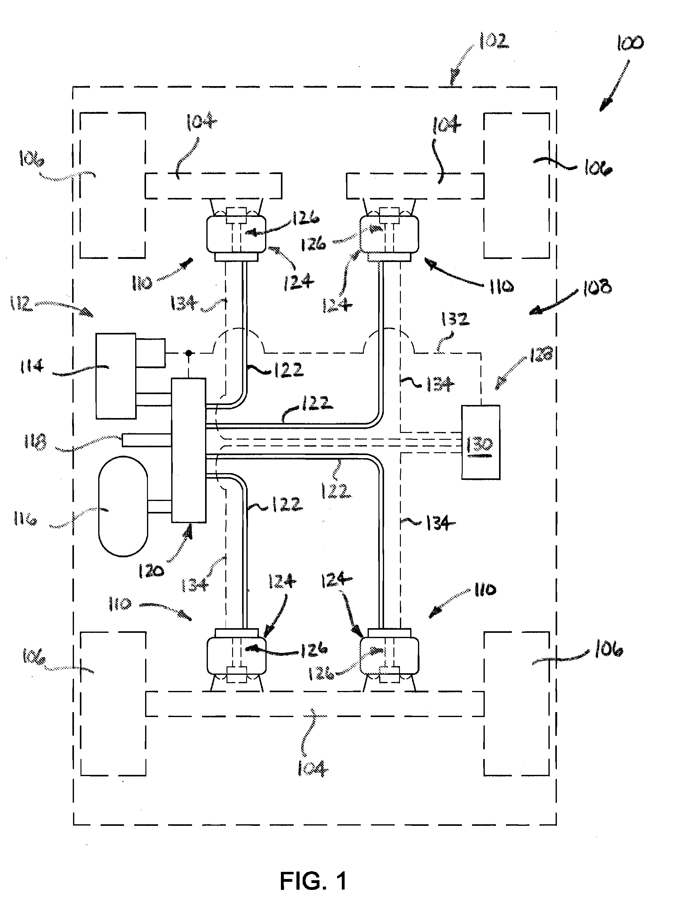
[0030]Turning now to the drawings wherein the showings are for the purpose of illustrating exemplary embodiments of the present novel concept and not for limiting the same, FIG. 1 illustrates a vehicle 100 having a sprung mass, such as a vehicle body 102, for example, and an unsprung mass, such as axles 104 and / or wheels 106, for example. Additionally, vehicle 100 can include a suspension system 108 that is operatively connected between the sprung and unsprung masses. Another example of sprung and unsprung masses with which a suspension system could be associated can include a cab or passenger compartment of a vehicle, such as a truck or tractor, for example, and the frame or structure upon which the cab or passenger compartment is supported.

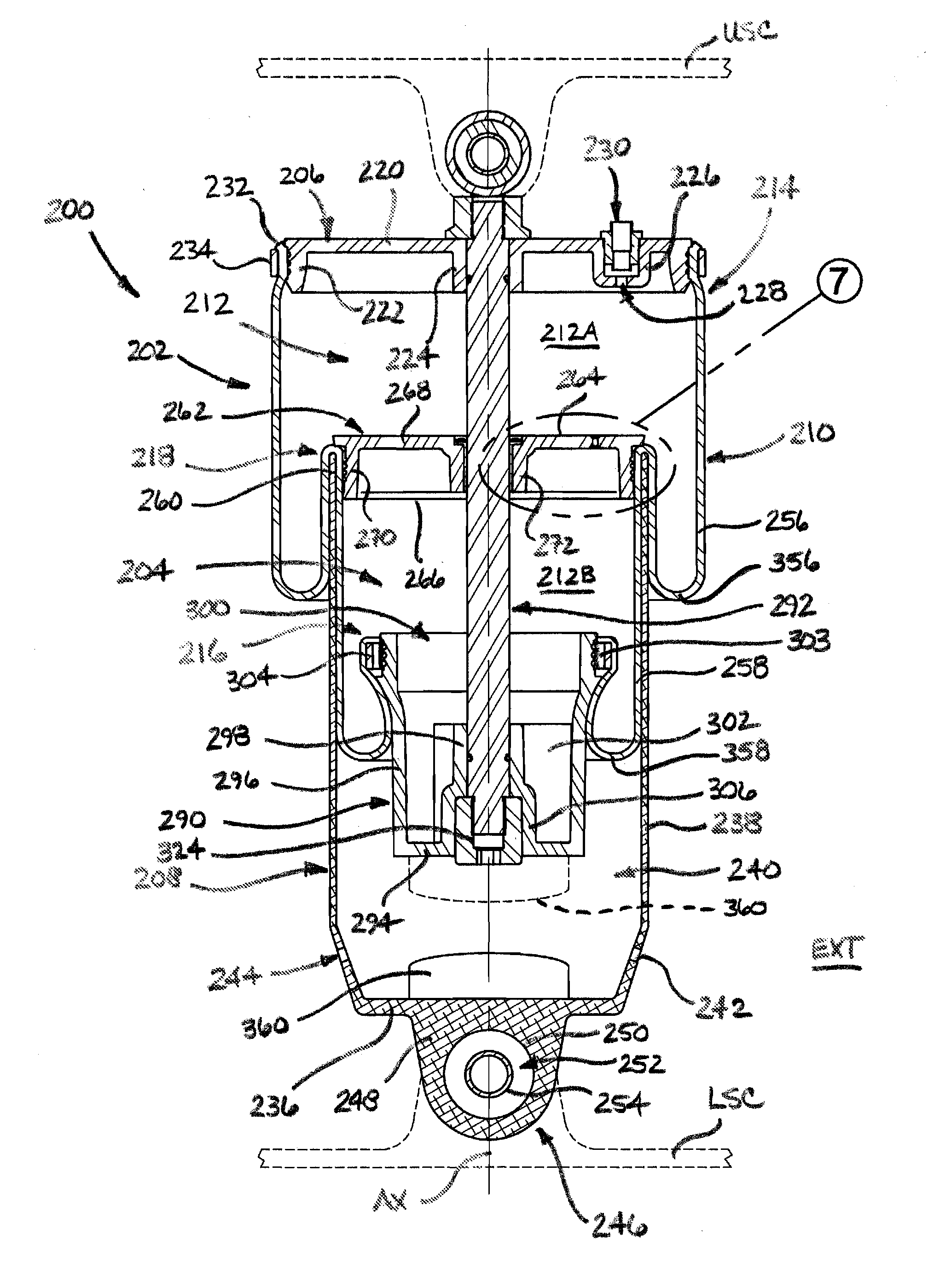
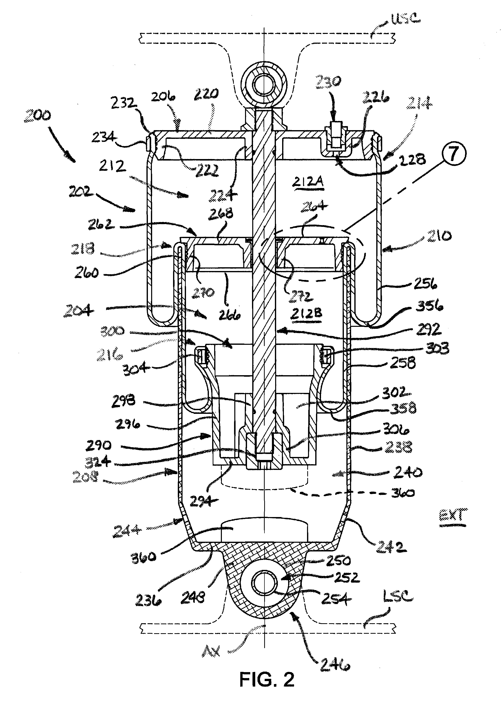
[0031]The suspension system can include a plurality of gas spring and gas damper assemblies 110 that are operatively connected between the sprung and unsprung masses of the vehicle. Assemblies 110 can be disposed between the sprung and unsprung ...


PUM

PropertyMeasurementUnit
Flexibilityaaaaaaaaaa

Abstract

A gas spring and gas damper assembly (1000) includes a gas spring assembly (1002) and a gas damper assembly (1004). The gas spring assembly (1002) includes a first wall portion (1006), a second wall portion (1008) disposed in spaced relation to the first wall portion (1006), and a flexible wall section (1010) connected therebetween. The gas damper assembly (1004) includes a third wall portion (1094) disposed in longitudinally-spaced relation to the first wall portion (1006), and a second flexible wall section (1104) connected between the second wall portion (1008) and the third wall portion (1094). A fourth wall portion (1070) is disposed between the first (1006) and second (1008) wall sections to define two pressurized gas chambers (1012, 1004). A damper rod (1130) connects at least the first (1006) and third (1094) wall portions. Methods are also included.

Description

BACKGROUND[0001]The present disclosure broadly relates to the art of spring devices and, more particularly, to a gas spring and gas damper assembly as well as a vehicle suspension system and a method of operating such a gas spring and gas damper assembly.[0002]A suspension system, such as may be used in connection with motorized vehicles, for example, can include one or more spring elements for accommodating forces and loads associated with the operation and use of the corresponding device (e.g., a motorized vehicle) to which the suspension system is operatively connected. In such applications, it is often considered desirable to utilize spring elements that operate at a lower spring rate, as a reduced spring rate can favorably influence certain performance characteristics, such as vehicle ride quality and comfort, for example. That is, it is well understood in the art that the use of a spring element having a higher spring rate (i.e. a stiffer spring) will transmit a greater magnit...

Claims


Application Information

Patent Timeline
IPC IPC(8): B60G15/12
CPCB60G15/12B60G2206/00B60G2202/32F16F2226/04B60G15/14B60G17/0521F16F9/0454F16F9/049B60G2202/242B60G2202/314B60G2204/1262Y10T29/49609B60G2206/40B60G2206/80
Inventor BOUNDS, JOSEPH A.
Owner FIRESTONE IND PROD COMPANY
Why Eureka
Try Eureka