Gas Charging Method and Gas Charging Apparatus for Bag Equipped with Gas Compartment Portion

a gas compartment and gas charging technology, which is applied in the direction of liquid handling, packaging goods, caps, etc., can solve the problems of difficult to improve productivity, gas compartment portion adhesion, front and rear film sheets that constitute, etc., and achieve the effect of smooth gas filling and no loss of productivity

Inactive Publication Date: 2014-09-11
TOYO JIDOKI CO LTD
View PDF4 Cites 45 Cited by
  • Summary
  • Abstract
  • Description
  • Claims
  • Application Information

AI Technical Summary

Benefits of technology

[0034]As seen from the above, in the present invention, a preliminary injection step is carried out before performing the gas filling step. With this preliminary injection step, compressed gas is injected into the gas compartment portion of a bag in advance. Thus, even if the front and rear film sheets of the gas compartment portion adhere to each other under the action of static electricity and the like, their adhesion can be released by this preliminary injection step (the adhered film sheets are separated and spread apart by the compressed gas injected into the gas compartment portion). Once the preliminary injection step is over, the gas injected into the gas compartment portion immediately escapes through the gas inlet (incision or opening), and the expanded gas compartment portion shrinks, assuming its original flat shape. However, due to the fact that the adhesion of the film sheets has been once released previously, the bag can be smoothly filled with gas when gas injection into the gas compartment portion is carried out again during the gas filling step. As a result, when the bag equipped with a gas compartment portion is conveyed in an intermittent manner, there is no need to increase the stop times when the bag is intermittently conveyed, and the gas compartment portion can be charged with compressed gas without loss of productivity. On the other hand, when the bag equipped with a gas compartment portion is conveyed in a continuous manner, there is no need to increase the distance for which the gas injection nozzle follows the bag.

Problems solved by technology

Accordingly, when this method is used for, for example, an intermittently rotating rotary packaging apparatus, it is difficult to improve the productivity compared to the gas charging method of Japanese Patent No. 4,771,785.
However, in a bag equipped with a gas compartment portion, static electricity may sometimes cause adhesion of the front and rear film sheets that constitute the gas compartment portion.
The problem that arises in such a case is that the gas compartment portion cannot be smoothly filled with gas, and as a result the amount of gas that fills the gas compartment portion is small, causing the expansion of the gas compartment portion to be insufficient, and making it impossible to sufficiently increase the shape retention and self-supporting properties of the bag.
This problem tends to be particularly acute for a bag in which the gas charging pathway of the gas compartment portion is made narrow (see Japanese Patent No. 5,104,073).
However, for increasing the time for injection, it is necessary to increase the stop time of the bag equipped with a gas compartment portion while it is being intermittently conveyed, and this causes a decrease in productivity of product bags to be unavoidable.

Method used


Image

  • Gas Charging Method and Gas Charging Apparatus for Bag Equipped with Gas Compartment Portion
  • Gas Charging Method and Gas Charging Apparatus for Bag Equipped with Gas Compartment Portion
  • Gas Charging Method and Gas Charging Apparatus for Bag Equipped with Gas Compartment Portion

Examples


Embodiment Construction

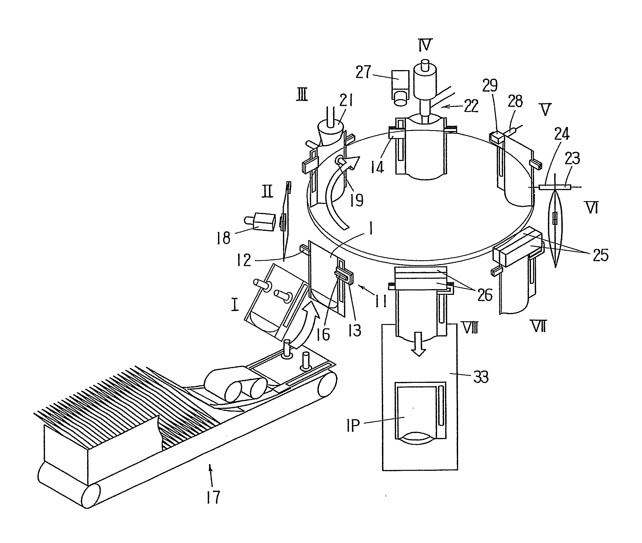
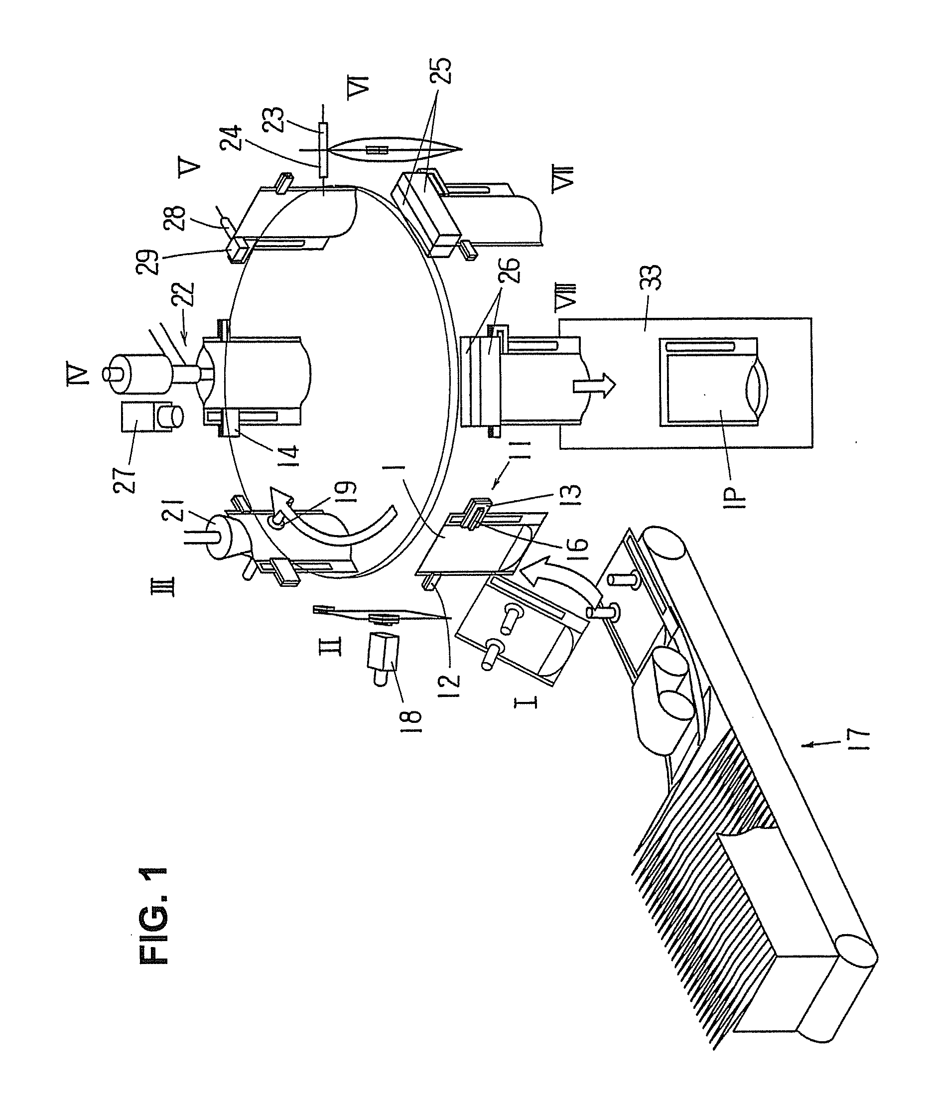
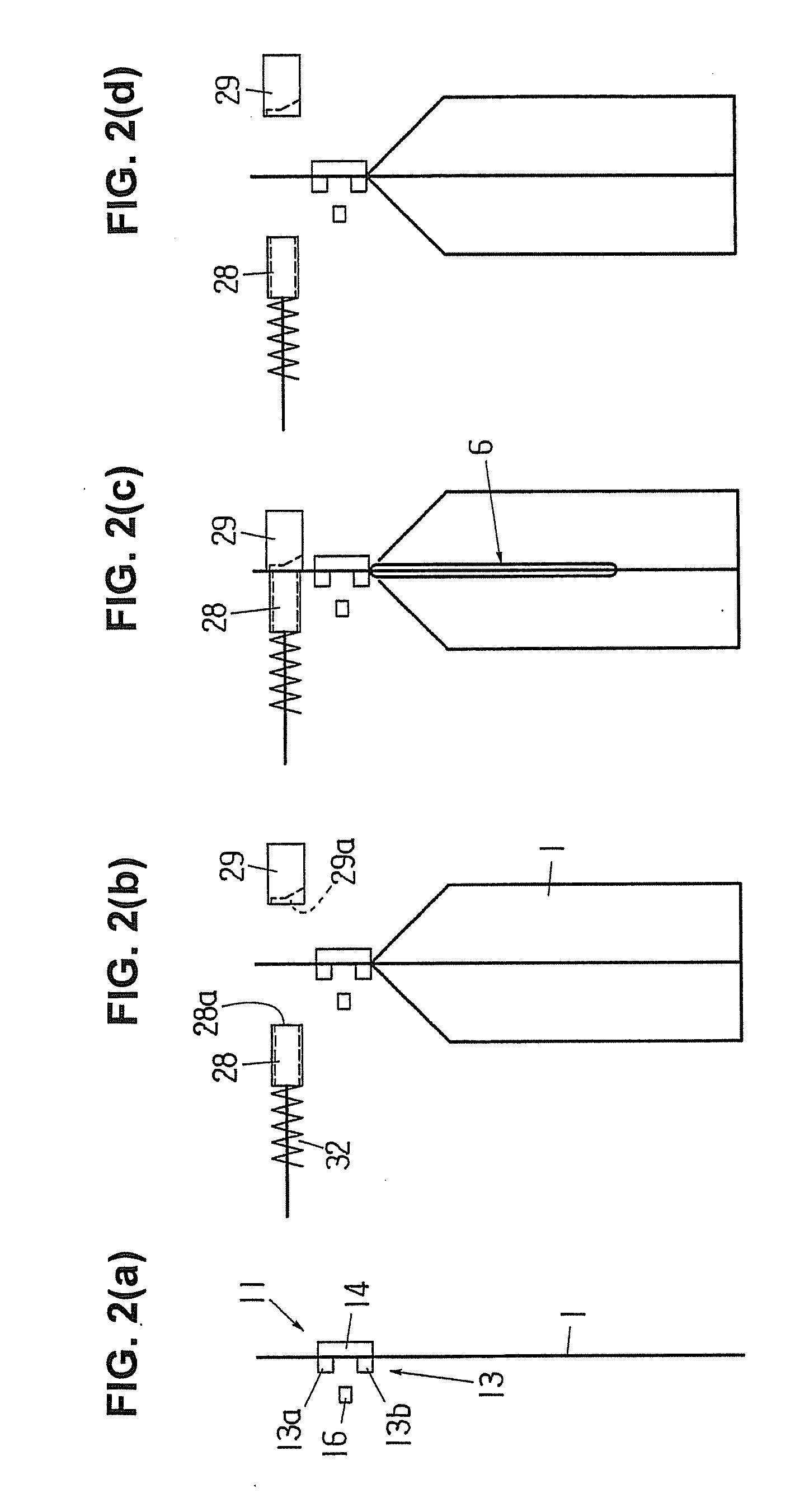
[0044]A gas charging method and apparatus of the present invention will be described below in more detail with reference to FIG. 1-FIG. 9(b).

[0045]FIGS. 5(a) and 5(b) show a bag 1 that is equipped with a gas compartment portion 6. The bag 1 is a bottom-gusseted self-supporting bag that is made up of front and rear film sheets, as well as a folded bottom film sheet. In the upper region X of the bag 1, the front and rear film sheets of the bag 1 are bonded together along the two lateral side edges, thereby forming seal portions 2, 3. At the upper edge, the front and rear film sheets are not bonded together, creating an open bag mouth 4. In the lower region Y of the bag 1, the front and rear film sheets are bonded along the two lateral side edges, thereby sandwiching the film sheet of the bottom portion, and, in addition, are bonded on the inside, where the film sheet of the bottom portion itself is folded inward. In the central portion, the front and rear film sheets are respectively ...


PUM

PropertyMeasurementUnit
areaaaaaaaaaaa
adhesionaaaaaaaaaa
shape retentionaaaaaaaaaa

Abstract

In a method and apparatus for charging a gas into a gas compartment portion (6) of a bag (1), after a pre-heating step which is performed in stop position (IV) so that the gas compartment portion of the bag is heated by a heated gas-blowing nozzle (27), a preliminary gas injection step for injecting gas into the gas compartment portion is performed by a gas blowing nozzle (28) and a receiving member (29) in stop position (V). Then, a gas filling step is carried out in stop position (VI) by gas injection nozzles (23, 24), and the incision (9) in the gas compartment portion is sealed in stop position (VII). In the following pre-heating step, the front and rear film sheets (7, 8) of the gas compartment portion are softened, and in the preliminary gas injection step, the film sheets are separated and their adhesion is eliminated.

Description

BACKGROUND OF THE INVENTION[0001]1. Field of the Invention[0002]The present invention relates to a method and apparatus for charging a gas into a bag and more particularly to a method and apparatus for charging a gas into a gas compartment portion provided in a sealed side edge portion of a bag.[0003]2. Description of the Related Art[0004]Japanese Patent No. 4,771,785 describes a method in which a bag having therein an integrally formed gas compartment portion extending in the longitudinal direction in a sealed side edge portion of the bag is intermittently conveyed along a predetermined bag conveying path, and the gas compartment portion is charged with gas while the bag is being conveyed.[0005]More specifically in this gas filing method of Japanese Patent No. 4,771,785, a bag, in which an incision or an opening (collectively called “gas inlet”) that places the exterior of the bag in communication with the interior of the gas compartment portion is formed in a film sheet constituti...

Claims


Application Information

Patent Timeline
Patent Type & Authority Applications(United States)
IPC IPC(8): B65B31/04B65B51/14
CPCB65B51/146B65B31/048B65B43/465B65B31/04B65B43/36B65B3/04B29L2031/7128B29C65/18B29C65/7841B29C65/7882B29C66/0342B29C66/1122B29C66/3452B29C66/43121B29C66/83221B29C66/849B65B55/20F17C5/06
Inventor YOSHIKANE, TOHRUSUNOUCHI, NORIKAZUKAWAMURA, KENJI
Owner TOYO JIDOKI CO LTD
Why Eureka
Try Eureka