
Sample cooling device

a cooling device and sample technology, applied in the field of sample cooling devices, can solve the problems of condensation, inability to completely seal, and increase the humidity inside the storage, and achieve the effect of preventing condensation

Active Publication Date: 2014-09-11
SHIMADZU CORP
View PDF1 Cites 24 Cited by
  • Summary
  • Abstract
  • Description
  • Claims
  • Application Information

AI Technical Summary

Benefits of technology

The present invention aims to prevent condensation in a sample container due to outside air flowing into it through a leak path. This is achieved by introducing the outside air into the storage while creating a positive pressure inside it. The outside air is then allowed to flow through a dehumidification heat transfer member to remove any moisture. The invention also suggests using Peltier elements and air feeding mechanisms for heat dissipation in a more cost-effective manner. Overall, the invention reduces the inflow of outside air into the sample storage, thus preventing condensation.

Problems solved by technology

However, on the other hand, since only the sample rack is cooled, moisture contained in the air inside the storage condenses on the cooled sample rack.
The leaking liquid is generated, for example, when a channel switching valve for introducing a sample for analysis into an analysis channel is exhausted, and the leakage of a mobile phase solvent thereby occurs.
The inside of the storage of the sample cooling device communicates with the outside air through such a leak path, and therefore, cannot be completely sealed.
Therefore, even when the dehumidification mechanism operates, the outside air flows into the storage from the outside thereof through the leak path, and the humidity inside the storage thereby increases.
As a result, condensation may occur in the sample rack cooling unit, the sample rack, and the sample container.

Method used


Image

  • Sample cooling device
  • Sample cooling device
  • Sample cooling device

Examples


Embodiment Construction

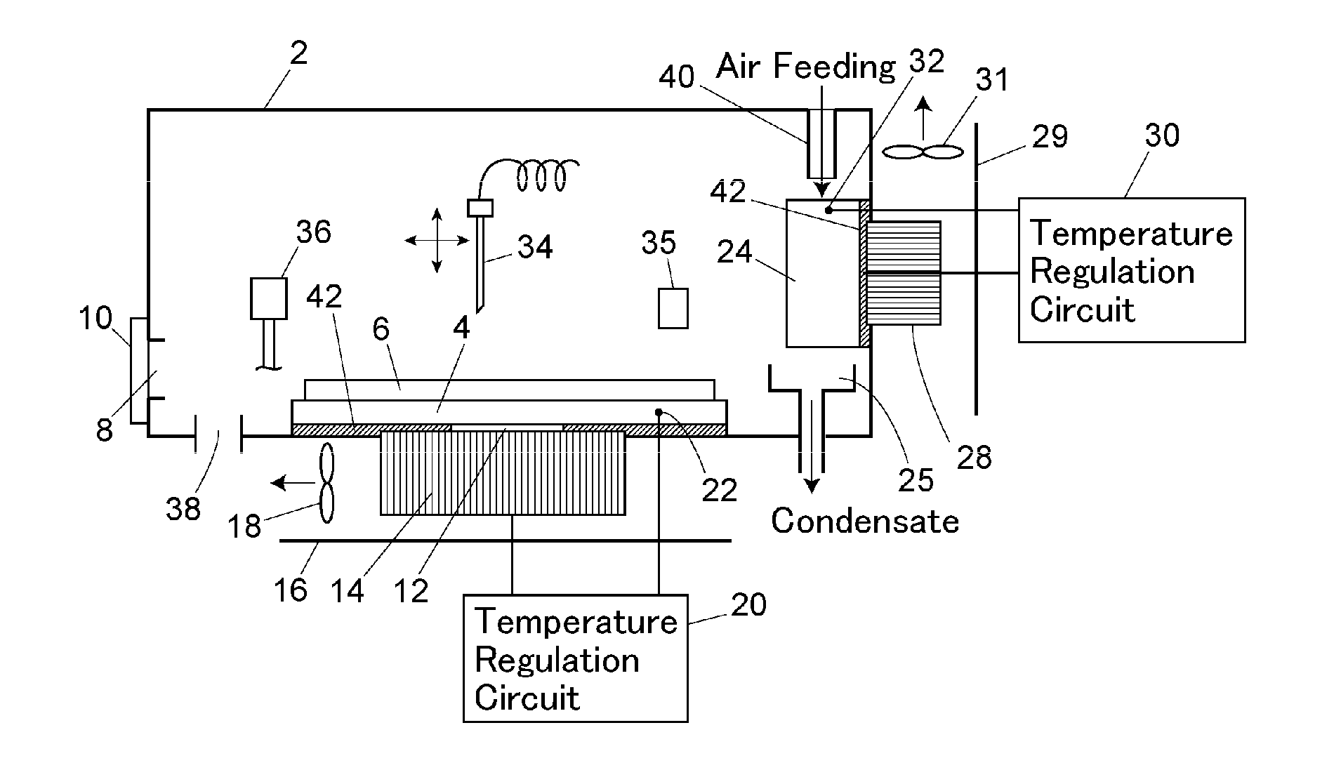
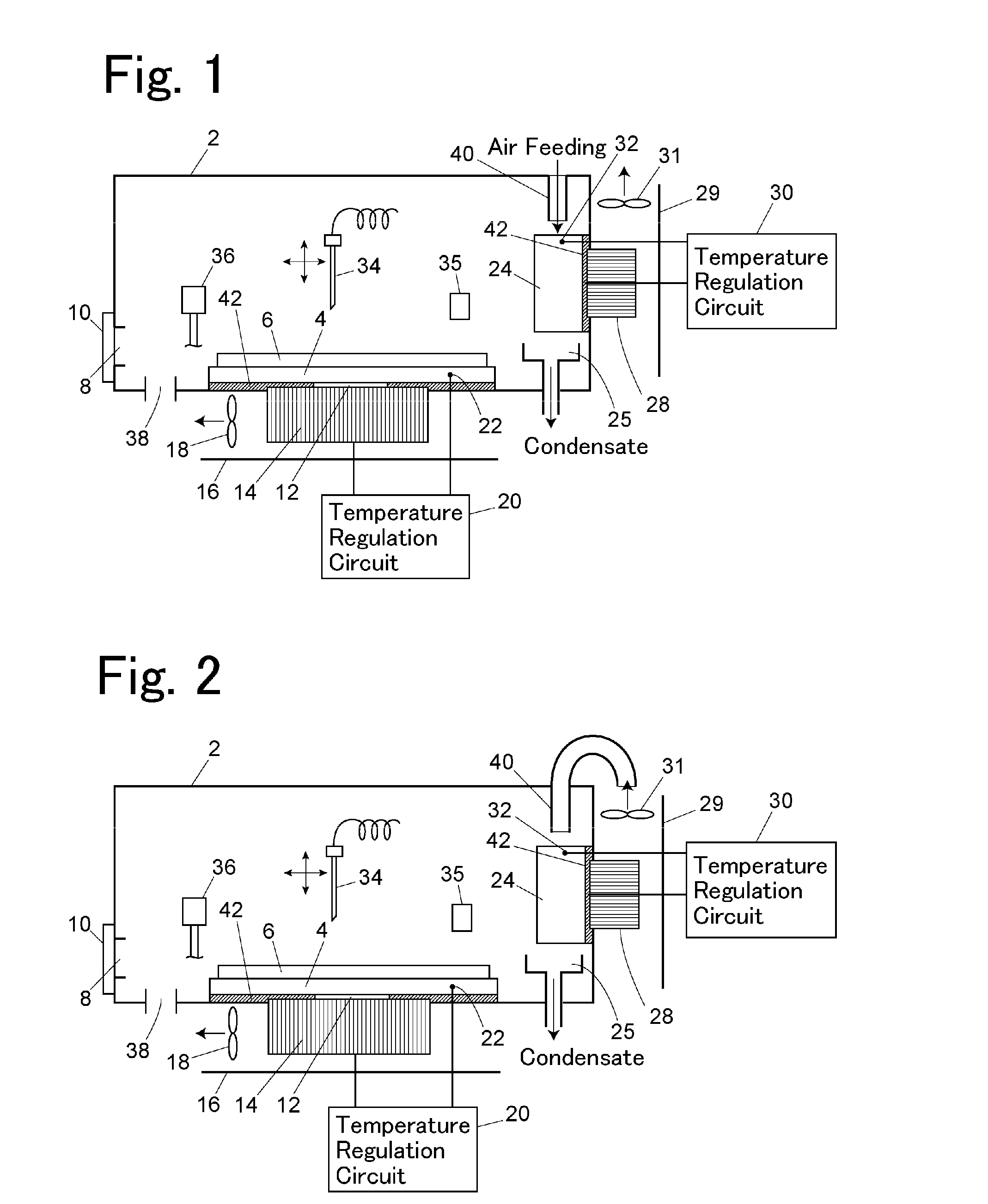
[0024]An embodiment of the present invention is illustrated in FIG. 1.

[0025]A sample cooling plate 4 as a first heat transfer member is provided in a lower part of a sample storage 2. A sample rack 6 is placed on the sample cooling plate 4. A plurality of sample containers, each of which stores therein a liquid sample, are put into the sample rack 6 in an aligned manner. Each of the sample containers is, for example, a small bottle made of glass. A sample rack insertion port 8 is provided on the front of the sample storage 2 (the left side in the drawing) for inserting and taking out the sample rack 6 into and from the sample storage 2. The sample rack insertion port 8 is closed by an openable / closable lid 10. The sample rack 6 is made of, for example, aluminum in order to improve the thermal conductivity thereof, and has a plurality of holes for inserting thereinto the sample containers.

[0026]In order to cool the sample rack 6 which is placed on the sample cooling plate 4, a Peltie...


PUM


Abstract

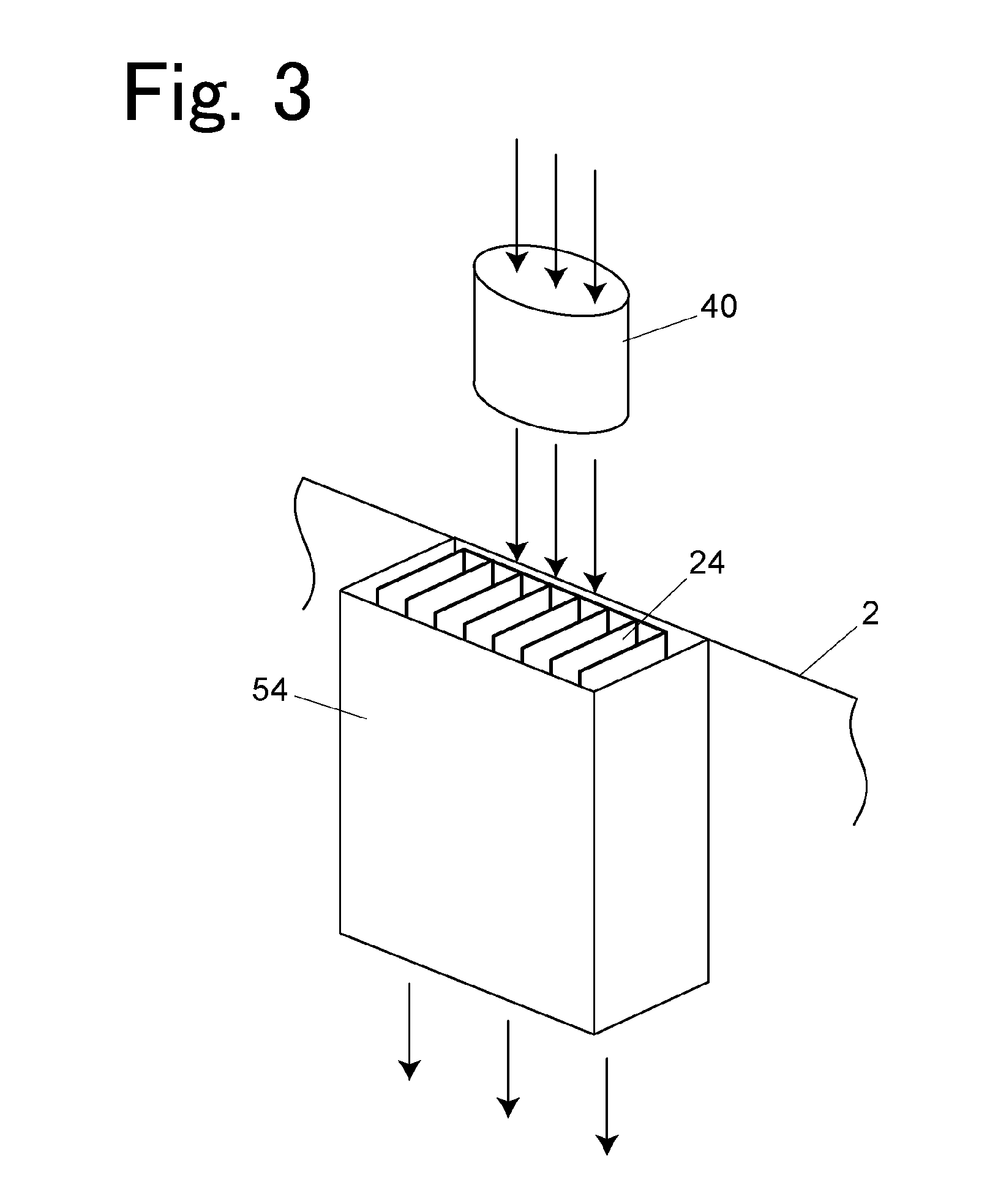
A sample cooling device is provided with, inside a sample storage which stores therein a sample rack, a first heat transfer member arranged at a position in contact with the sample rack, a second heat transfer member which cools the inside of the sample storage, and a condensate discharge mechanism which discharges condensate condensing on the second heat transfer member to the outside of the sample storage. An internal space of the sample storage is not sealed due to the existence of a leak path for air formed between the inside and the outside of the sample storage, the leak path including at least the channel. The sample storage includes an outside air introduction unit which forcibly blows the outside air into the internal space so that the pressure inside the sample storage becomes higher than the outside pressure thereof. The position and the direction of an outside air outlet of the outside air introduction unit inside the sample storage are set so that the outside air blown into the sample storage directly heads for the second heat transfer member.

Description

BACKGROUND OF THE INVENTION[0001]1. Field of the Invention[0002]The present invention relates to a sample cooling device which cools a sample before analysis in an analyzer such as a liquid chromatograph analyzer.[0003]2. Description of the Related Art[0004]A sample cooling system of a sample cooling device which cools a sample before analysis includes a direct cooling system and an air cooling system. In the direct cooling system, a sample rack in which a sample container which stores therein a sample is set is placed on a sample rack placing unit that has been cooled to thereby directly cool the sample container through the sample rack (see Japanese Unexamined Patent Application Publication No. 2000-74802 and Japanese Unexamined Patent Application Publication No. 2001-12839). In the air cooling system, air inside a sample storage is cooled and circulated by a cooling Peltier element to thereby cool the entire air inside the sample storage (see Japanese Unexamined Patent Applicatio...

Claims


Application Information

Patent Timeline
IPC IPC(8): F25D31/00
CPCF25D31/006F25D11/00A01N1/0242A01N1/0252F25B21/02F25D17/08F25D21/04F25D2317/0411G01N25/145
Inventor TANAKA, SHINJI
Owner SHIMADZU CORP
Learn More