Threaded member capable of detecting tightening force

a threaded member and tightening force technology, applied in the direction of force/torque/work measurement apparatus, screws, instruments, etc., can solve the problems of insufficient sensitivity of threaded members, affecting the structural strength of buildings and the operation effect of mechanical equipment, and threatening the safety of users' lives and properties, so as to achieve the effect of sensitive detection of strain capacity of head sections and easy deformation

Active Publication Date: 2014-09-11
KABO TOOL COMPANY
View PDF8 Cites 13 Cited by
  • Summary
  • Abstract
  • Description
  • Claims
  • Application Information

AI Technical Summary

Benefits of technology

[0009]It is therefore a primary object of the present invention to provide a threaded member capable of detecting tightening force. A sink section is formed between the head section and threaded rod section of the threaded member. When a tightening force is applied to the head section to strain the head section relative to the threaded rod section, due to the sink section

Problems solved by technology

However, when the threaded member is applied to a current large-scale building, sophisticated building, sophisticated equipment or highly stressed site, in the case that the threaded member is over-tightened or under-tightened, the structural strength of the building and the operation effect of the mechanical equipment will

Method used


Image

  • Threaded member capable of detecting tightening force
  • Threaded member capable of detecting tightening force
  • Threaded member capable of detecting tightening force

Examples


Embodiment Construction

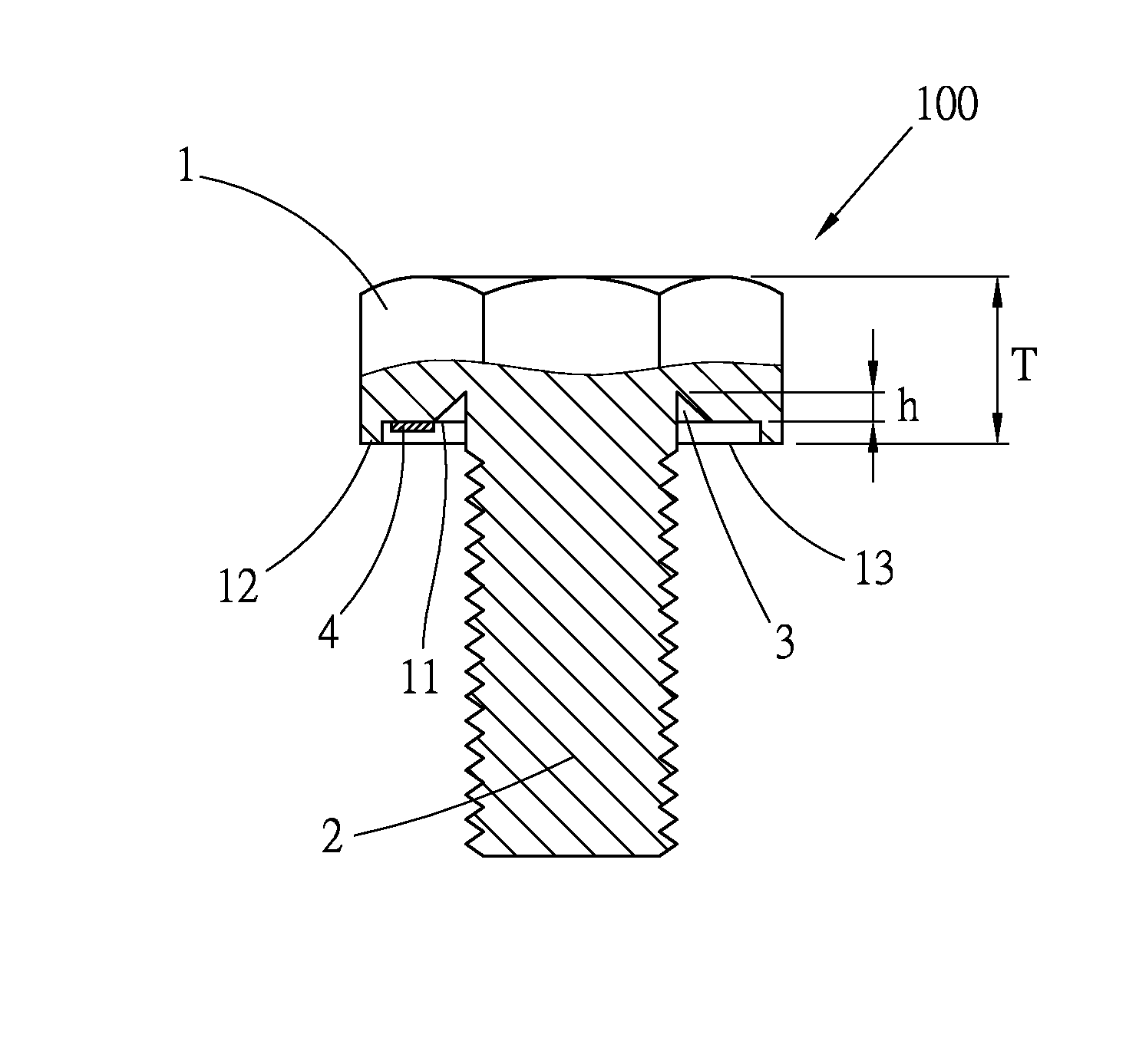
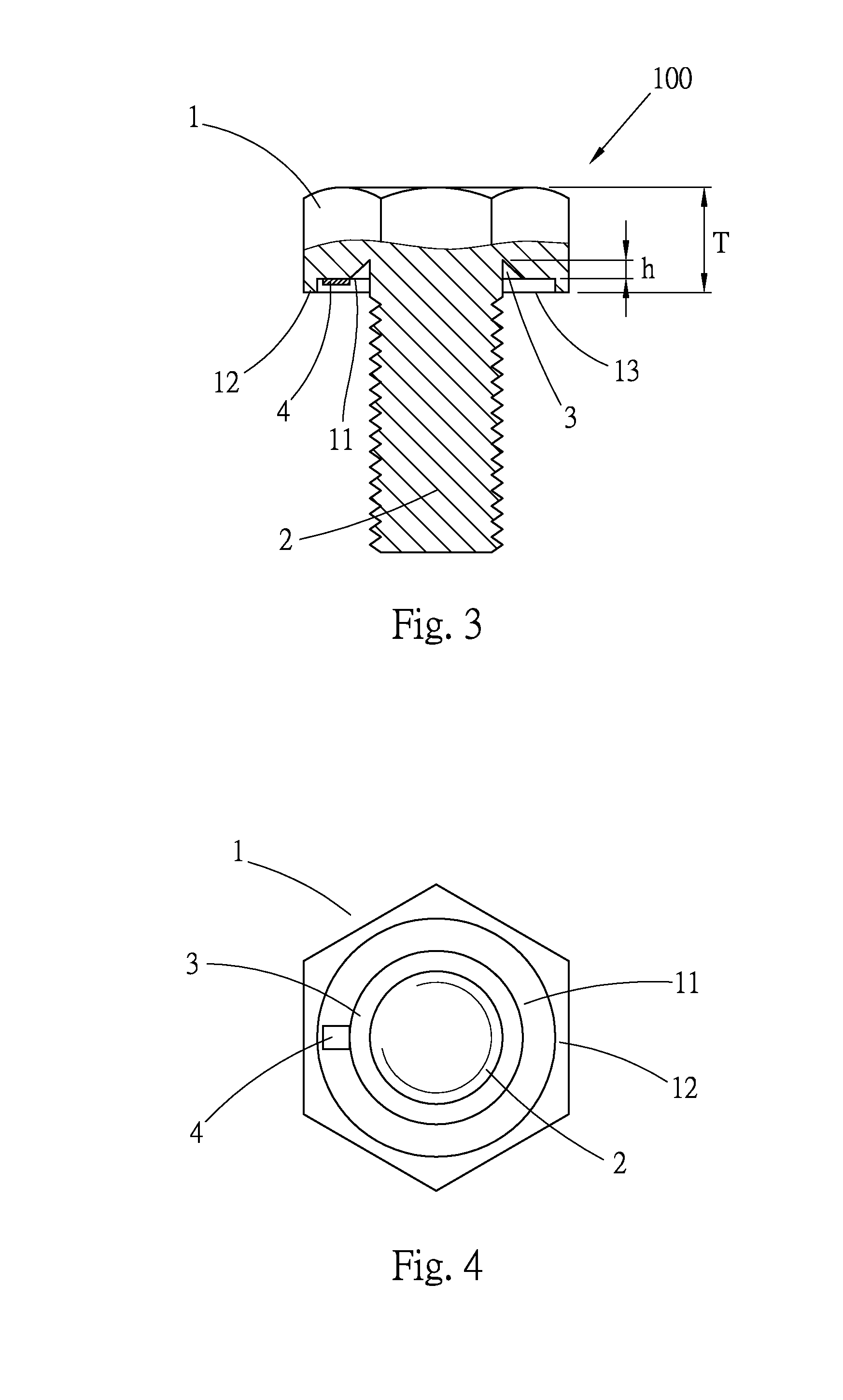
[0022]Please refer to FIGS. 3 and 4. According to a first embodiment, the threaded member 100 of the present invention includes a head section 1, a threaded rod section 2 and a strain sensor 4. The head section 1 has a bottom face 11 and a skirt section 12 downward protruding from a periphery of the bottom face 11. The skirt section 12 is formed along the periphery of the bottom face 11. A receiving space 13 is formed under the head section 1 between the skirt section 12 and the bottom face 11. The threaded rod section 2 is disposed at a center of the bottom face 11 of the head section 1. A thread is formed on outer circumference of the threaded rod section 2.

[0023]A sink section 3 is formed on the bottom face 11 of the head section 1 in adjacency to the threaded rod section 2. The bottom face 11 is inward recessed from the receiving space 13 to form the sink section 3. In this embodiment, the sink section 3 is, but not limited to, an annular groove. For example, the bottom face 11 ...


PUM


Abstract

A threaded member capable of detecting tightening force includes a head section, a threaded rod section and at least one strain sensor. The head section has a bottom face, a skirt section and a receiving space. The threaded rod section is disposed under the bottom face of the head section. A sink section is formed on the bottom face of the head section. The strain sensor is disposed on the bottom face of the head section and positioned in the receiving space. Due to the sink section, when the head section is strained and deformed, the strain sensor can sensitively and precisely detect the strain capacity of the head section and provide the tightening force of the threaded member for a user to more precisely tighten the threaded member.

Description

BACKGROUND OF THE INVENTION[0001]1. Field of the Invention[0002]The present invention relates generally to a threaded member capable of detecting tightening force, and more particularly to a threaded member, which has higher strain sensitivity for more precisely detecting the tightening extent of the threaded member.[0003]2. Description of the Related Art[0004]A threaded member is used to tighten a work piece. In engineering, a threaded member is often used to tighten or connect two or more articles with each other. In simple practice, the threaded member is only tightened without noting the tightening torque applied to the threaded member.[0005]However, when the threaded member is applied to a current large-scale building, sophisticated building, sophisticated equipment or highly stressed site, in the case that the threaded member is over-tightened or under-tightened, the structural strength of the building and the operation effect of the mechanical equipment will be affected. This...

Claims


Application Information

Patent Timeline
IPC IPC(8): G01L5/24
CPCG01L5/24F16B31/02
Inventor HSIEH, CHIH-CHING
Owner KABO TOOL COMPANY
Why Eureka
Try Eureka