Switch
a push-button switch and switch technology, applied in the field of switches, can solve the problems of difficult to dispose of leds, difficult to enlarge the dimensions of appearance, and difficult to change the position of the member in the center of the key switch
- Summary
- Abstract
- Description
- Claims
- Application Information
AI Technical Summary
Benefits of technology
Problems solved by technology
Method used
Image
Examples
first embodiment
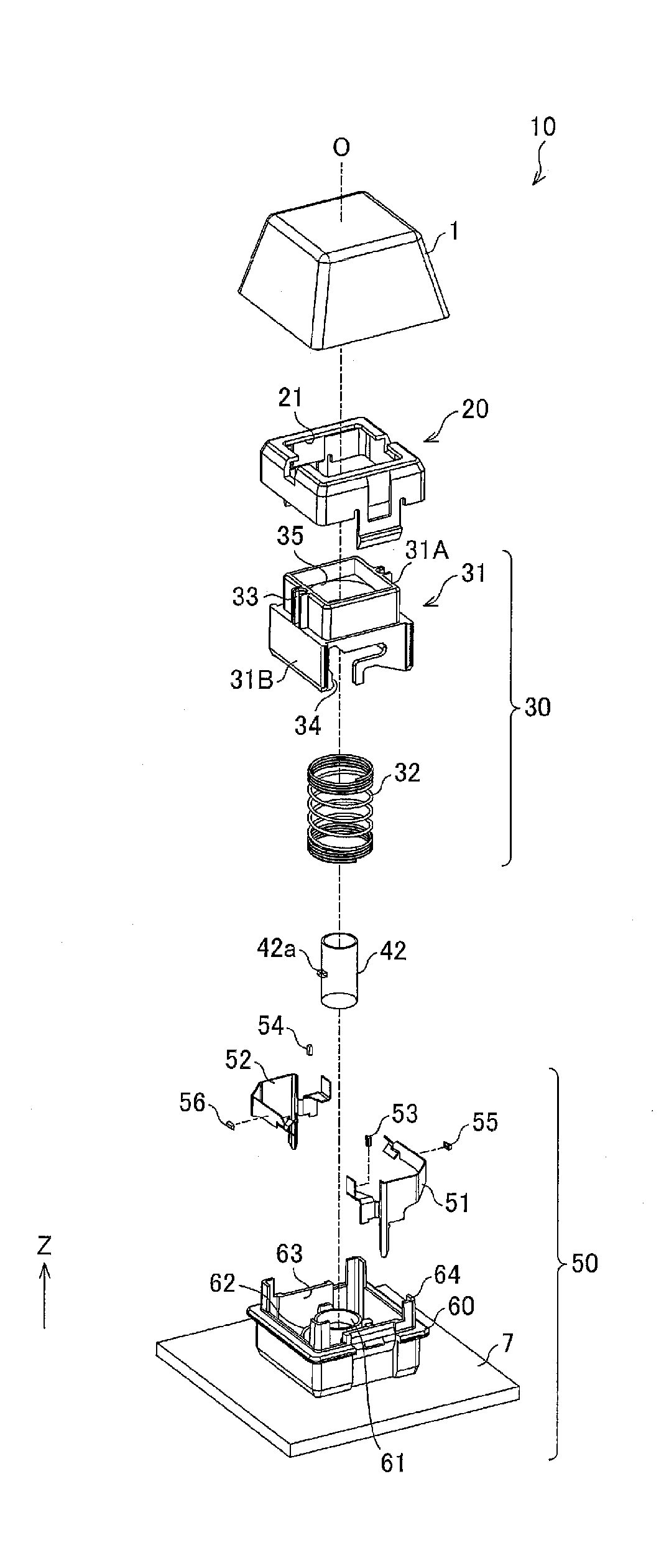
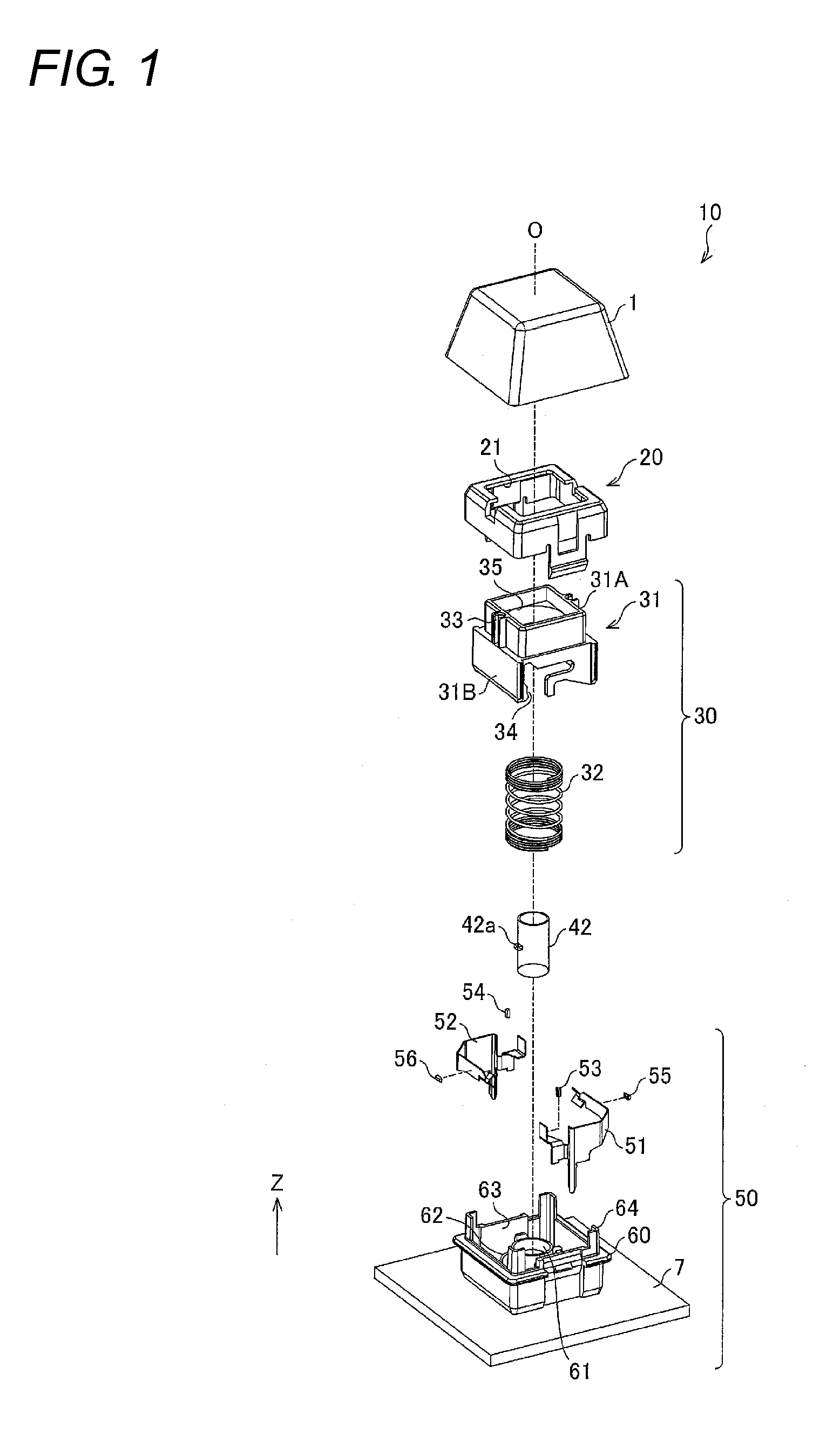
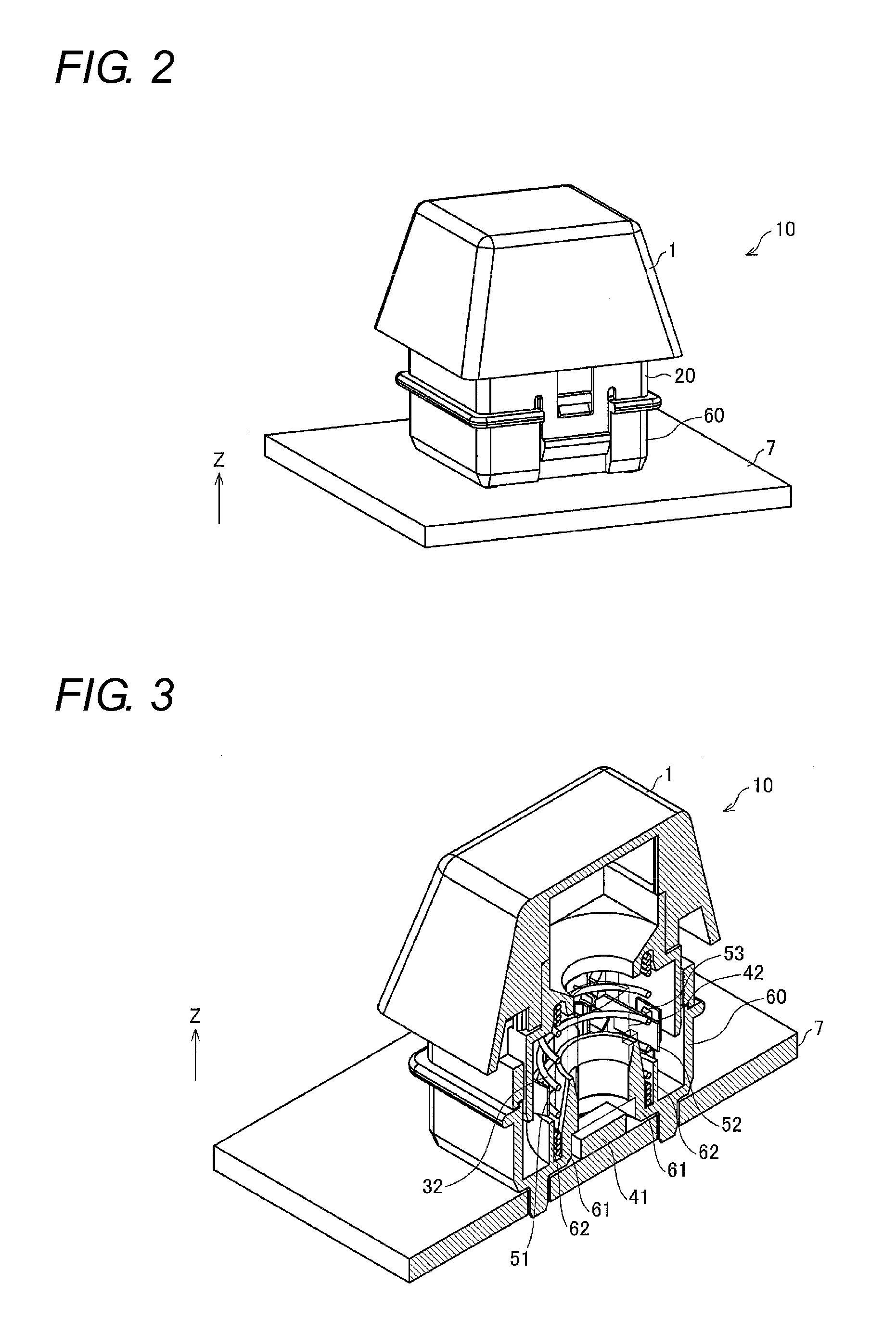
[0023]Hereinafter, embodiments of the present invention will be described with reference to the drawings. FIG. 1 is an exploded perspective view illustrating a configuration of a push-button switch 10 according to a first embodiment. FIG. 2 is a perspective view illustrating an appearance of the push-button switch 10. FIG. 3 is a sectional perspective view illustrating the configuration of the push-button switch 10. FIGS. 2 and 3 illustrate a non-pressing state.
[0024]The push-button switch 10 of the first embodiment is a contact type switch, and has the configuration particularly suitable for a lighted switch assembled in a keyboard, an industrial operation panel, an operation panel of a business-use video instrument, and a consumer product.
[0025]As illustrated in FIGS. 1 to 3, the push-button switch 10 includes a keytop 1, an upper case 20 (casing), a plunger unit 30, a light source 40, a contact mechanism 50, a lower case 60 (casing), and a board 7. The upper case 20 is fitted in ...
second embodiment
[0072]A second embodiment of the present invention will be described below with reference to FIG. 9. For the sake of convenience, elements of the second embodiment equivalent to those of the first embodiment are designated by consistent reference numerals, and a detailed description thereof is omitted, reference being made to the above-description of the first embodiment. FIG. 9 is a sectional perspective view illustrating a configuration of the push-button switch 10 of the second embodiment. FIG. 9 illustrates the non-pressing state.
[0073]In the push-button switch 10 of the first embodiment, the light source 40 including the LED 41 and the light guide rod 42 is disposed in the central space of the lower case 60, and the central space is ensured by the movable plates 51 and 52. However, the light source 40 disposed in the central space of the lower case 60 is not limited to the configuration including the light guide rod 42. The configuration of the light source 40 is properly set a...
third embodiment
[0076]A third embodiment of the present invention will be described below with reference to FIG. 10. For the sake of convenience, elements of the third embodiment equivalent to those of the first and / or second embodiments are designated by consistent reference numerals, and a detailed description thereof is omitted, reference being made to the above-description of the earlier embodiments. FIG. 10 is a sectional perspective view illustrating a configuration of the push-button switch 10 of the third embodiment. FIG. 10 illustrates the non-pressing state.
[0077]In the push-button switch 10 of the first and second embodiments, the light source 40 emitting the light toward the keytop 1 is disposed in the central space of the lower case 60, and the central space is ensured by the movable plates 51 and 52. However, the member disposed in the central space of the lower case 60 is not limited to the light source, but the member may properly be set according to the dimension of the push-button...
PUM
 Abstract
Description
Claims
Application Information
 - R&D
- Intellectual Property
- Life Sciences
- Materials
- Tech Scout
- Unparalleled Data Quality
- Higher Quality Content
- 60% Fewer Hallucinations
Browse by: Latest US Patents, China's latest patents, Technical Efficacy Thesaurus, Application Domain, Technology Topic, Popular Technical Reports.
© 2025 PatSnap. All rights reserved.Legal|Privacy policy|Modern Slavery Act Transparency Statement|Sitemap|About US| Contact US: help@patsnap.com


