Stator or rotor with interlaced wire groups forming an intertwined wave winding

a technology of interlaced wire and intertwined wave, which is applied in the direction of windings, dynamo-electric components, synchronous machines, etc., can solve the problems of increased deficiency, increased production difficulty of machines, and lack of uniform thickness

Active Publication Date: 2014-09-11
SCHAEFFLER ELMOTEC STATOMAT GMBH
View PDF20 Cites 8 Cited by
  • Summary
  • Abstract
  • Description
  • Claims
  • Application Information

AI Technical Summary

Benefits of technology

[0015]The invention offers the advantage that the wave winding can be assembled from two wire groups that are to be prefabricated each in one ply, with straight segments offset transversely from the central plane, and [the wire groups can then be intertwined / interlaced?] with all the wires. The head portions alternatingly jump from a radially inner ply to a radially outer ply and back again, and thus rest obliquely to the circumferential direction of the stator or rotor. Nevertheless, the wires are bent only locally at the transitions from the straight segments to the head portions and at the apexes thereof, specifically preferably only about bending axes extending longitudinally of the strand and transversely thereto. In this way, rectangular wires too can be aligned uniformly in the head portions, so that after assembly, they point radially outward and inward with diametrically opposed side faces. By the deformation at the apex of the head portions, which has the effect that in top view on one side of the apex one side face and on the other side the diametrically opposed side face of the rectangular wire forms the outer face of the head portion, the wire becomes plastically deformed and after that maintains its shape.

Problems solved by technology

Although a double or two-ply layer formed of both winding halves located one above the other is supposed to have the thickness of twice the wire thickness, at certain points three wires intersect at such close spacing that a certain lack of uniformity in thickness occurs, and this deficiency increases when there are a plurality of layers.
No production method is disclosed, but if, as is normally desired, the prefabricated wave winding shall extend multiple times about the circumference of a stator or rotor and thus form a plurality of layers, in those areas where the transition from one layer to the next takes place, an irregularity must be incorporated into the strand of interlaced wires, making production by machine more difficult.
Because of the residual intrinsic elasticity, however, they do not rest flat there, nor are they pressed from outside against these faces, and they are not retained in slots.
The bending of the wires about the edges that define the gable-shaped end faces, in conjunction with the bending for attaining the axial inclination of the wire windings, causes torsion of the rectangular wires throughout the area of the head portion, which proves harmful in the phase between when the coil is removed from the former and the flat pressing is done.
However, both the torsional stress in the wire and the bending edges extending obliquely to its longitudinal edges cause twisting about the longitudinal axis of the wire and bends, so that upon the flat pressing, the wire portions located one above the other or intersecting one another are in part pressed with their side edges instead of with the side faces, against one another, and the parallel course of the wires in the head portion region is not assured, either.

Method used


Image

  • Stator or rotor with interlaced wire groups forming an intertwined wave winding
  • Stator or rotor with interlaced wire groups forming an intertwined wave winding
  • Stator or rotor with interlaced wire groups forming an intertwined wave winding

Examples


Embodiment Construction

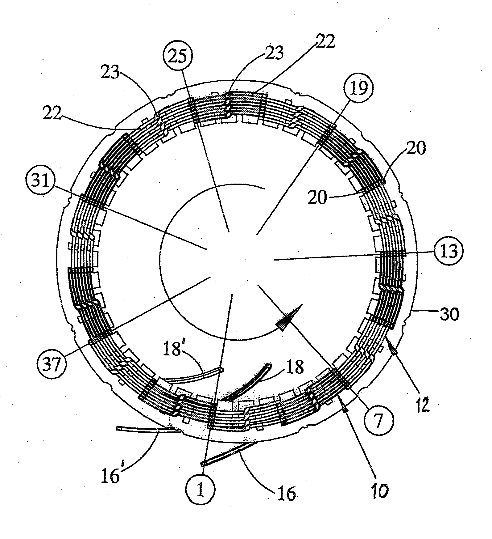
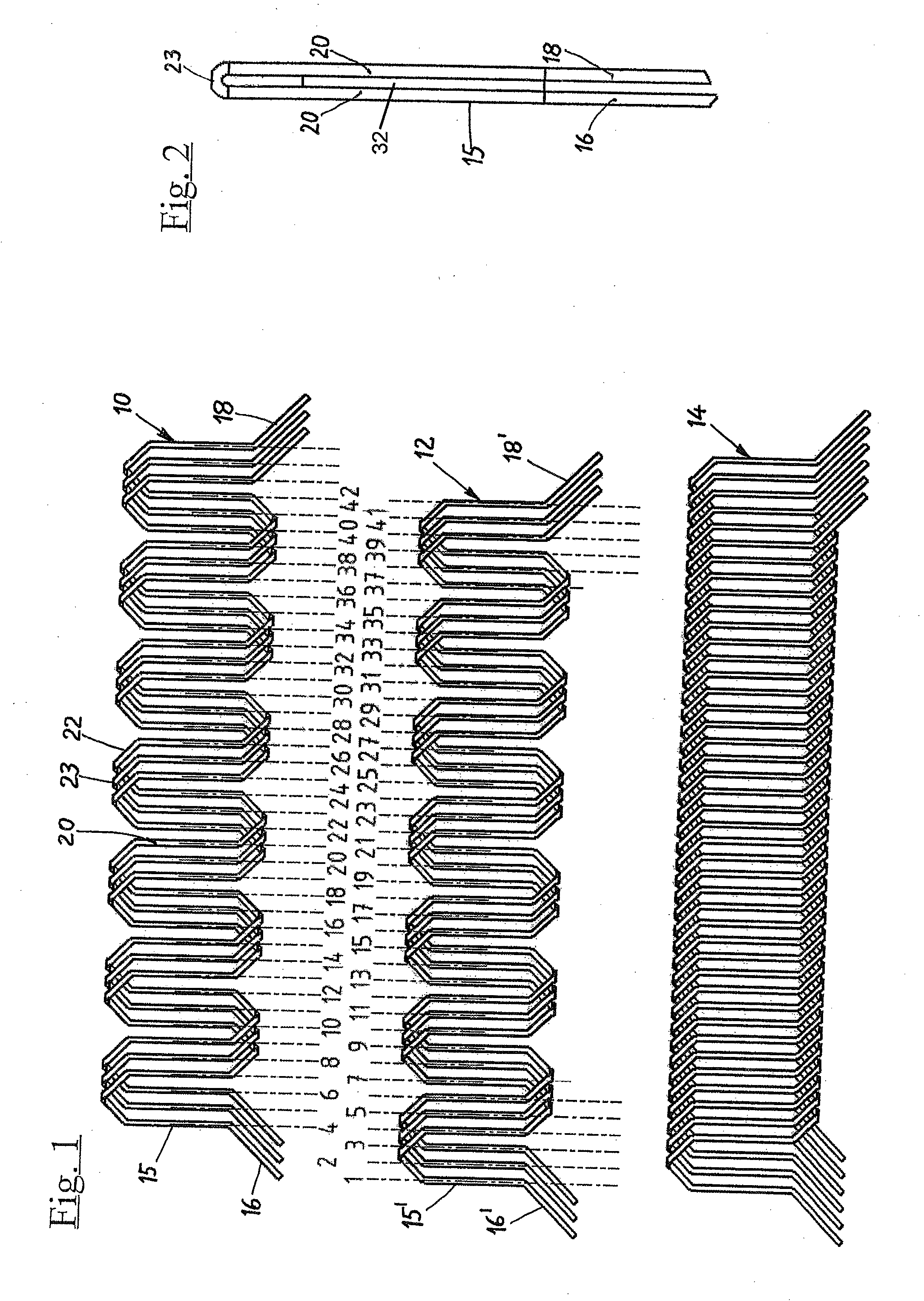
[0027]As shown in FIG. 1, first, two wire groups 10 and 12, comprising parallel wires formed and interlaced with one another, are produced, which are then put together and intertwined by winding onto one another to form a wave winding identified in its entirety by reference numeral 14, which is introduced into a stator or rotor, i.e., an electrical element for an electrical device hereafter exemplarily depicted as stator 30.

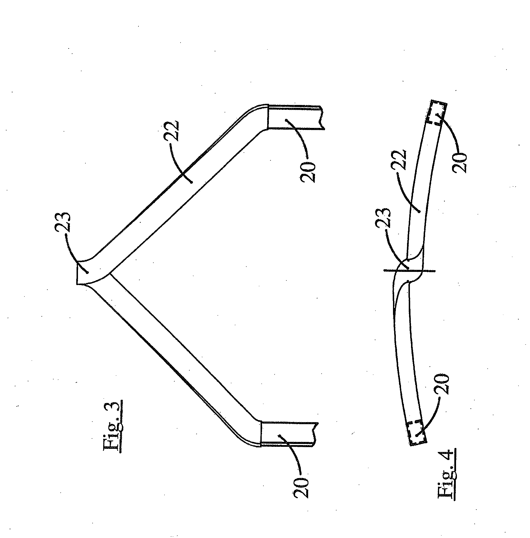
[0028]The two wire groups 10 and 12, in this example, match identically, but may also have differently shaped head portions. They each comprise three parallel wires 15, 15′ whose beginnings are marked 16 and 16′ and whose end is marked 18 and 18′, respectively. In each of the two wire groups 10, 12, the three wires 15, 15′ extend in wavelike fashion between their respective beginning and end and in the process form rectilinear straight segments 20, to be introduced into the stator or rotor slots, and head portions 22 which join two adjacent straight segments 20 o...


PUM

PropertyMeasurementUnit
widthaaaaaaaaaa
circumferenceaaaaaaaaaa
lengthaaaaaaaaaa

Abstract

The disclosed stator or rotor has a distributed wave winding, in which the wires are associated in pairs lying with straight segments in the same slots. Head portions of two successive straight segments of each wire of a pair protrude from opposite ends of slots. For forming two wire groups, a plurality of coil windings are simultaneously created by winding up n parallel wires with intermediate spacing onto a striplike former that is rotatable about its longitudinal axis. From each of the parallel wires one straight segment and one end turn are doubled by being bent over with the wire length of a head portion, and then head portions are formed and the wires interlaced. Finally, the two wire groups are wound onto one another and thereby intertwined with one another, and then introduced as an entire intertwined wave winding strand into the stator or rotor slots.

Description

CROSS REFERENCE TO RELATED APPLICATIONS[0001]This application is a divisional of application Ser. No. 12 / 423,277, filed Apr. 14, 2009, now U.S. Pat. No. 8,667,666 issued Mar. 11, 2014 (which is hereby incorporated by reference).FIELD OF THE INVENTION[0002]The invention relates to a method for producing a stator or rotor, i.e., electrical elements, for electrical machines, having a distributed wave winding, the wires of which wave winding are shaped continuously in wavelike fashion into straight segments introduced into the slots of the stator or rotor and head portions, each head portion joining two adjacent straight segments of one wire and protruding past an end face of the stator or rotor, in which the head portions of wires, associated in pairs occupying the same slots, protrude from opposite ends of the slots receiving two successive straight segments of the associated wires.[0003]The invention further relates to a stator or rotor (electrical element) of an electrical machine h...

Claims


Application Information

Patent Timeline
Patent Type & Authority Applications(United States)
IPC IPC(8): H02K3/12
CPCH02K3/12H02K15/0478Y10T29/49009Y10T29/49012Y10T29/49073
Inventor SADIKU, SADIKWITWER, KEITH A.
Owner SCHAEFFLER ELMOTEC STATOMAT GMBH
Why Eureka
Try Eureka