Impedance compensation circuit
a compensation circuit and circuit technology, applied in the field of manufacture of components, can solve the problems of low reflection of signals, poor return loss of 8-10 db, and the end of externally powered amplifiers, and achieve the effects of low capacitance, low capacitance, and relatively high capacitan
- Summary
- Abstract
- Description
- Claims
- Application Information
AI Technical Summary
Benefits of technology
Problems solved by technology
Method used
Image

Examples
Embodiment Construction
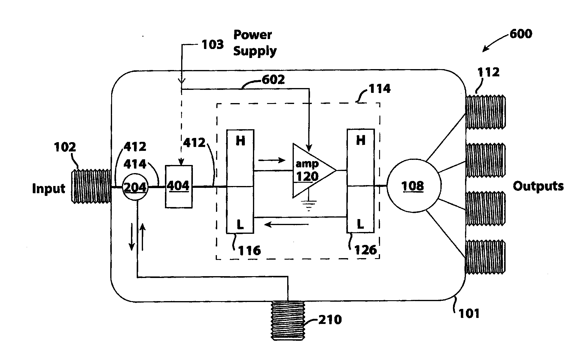
[0041]FIG. 4 shows a drop amp in accordance with the present invention 400. Unlike the prior art series switch on an input diplexer input or the prior art electronic switch between the amplifier and the input diplexer high frequency output, the present invention utilizes embodiments of a variable impedance device 404 to compensate for drop amp input impedance when there is a power outage and amplifier impedance change. As shown, the variable impedance device 404 is located in line (connects between points “a” and “b”) between the directional coupler 204 and the filter block 114. A first line 412 interconnects the input port 102 and the directional coupler, a second line 414 interconnects the directional coupler and the variable impedance device 404, and a third line 416 interconnects the variable impedance device and the input diplexer.
[0042]FIGS. 5A-5C show variable impedance circuits 500A, 500B, 500C for use with the present invention. As seen, each of these circuits includes one ...
PUM
 Abstract
Description
Claims
Application Information
 - R&D Engineer
- R&D Manager
- IP Professional
- Industry Leading Data Capabilities
- Powerful AI technology
- Patent DNA Extraction
Browse by: Latest US Patents, China's latest patents, Technical Efficacy Thesaurus, Application Domain, Technology Topic.
© 2024 PatSnap. All rights reserved.Legal|Privacy policy|Modern Slavery Act Transparency Statement|Sitemap