Channel-type supervised node positioning method for a wireless network

a wireless network and wireless network technology, applied in the field of wireless sensor networks, can solve the problems of rare and severe limitations of the conventional wls positioning algorithm, receivers with limited sensitivity in practice, and rarely met in practi

Active Publication Date: 2014-09-11
COMMISSARIAT A LENERGIE ATOMIQUE ET AUX ENERGIES ALTERNATIVES
View PDF10 Cites 23 Cited by
  • Summary
  • Abstract
  • Description
  • Claims
  • Application Information

AI Technical Summary

Problems solved by technology

The conventional WLS positioning algorithm suffers from several severe limitations.
However, this condition is rarely met in practice as the environment and the channel configuration are often unknown or may change as a function of time.
Second, the receivers have in practice a limited sensitivity (i.e. a finite detection threshold if Pth is labeled in dBm).
A subsidiary problem is to propose a node positioning algorithm that further allows for the use of real receivers with limited power sensitivity.

Method used


Image

  • Channel-type supervised node positioning method for a wireless network
  • Channel-type supervised node positioning method for a wireless network
  • Channel-type supervised node positioning method for a wireless network

Examples


first embodiment

[0043]FIG. 3 diagrammatically represents a node positioning algorithm according to the invention.

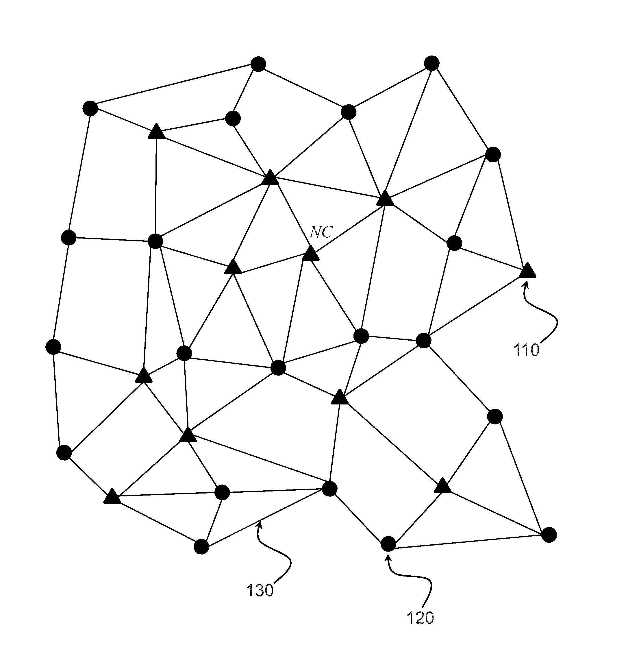
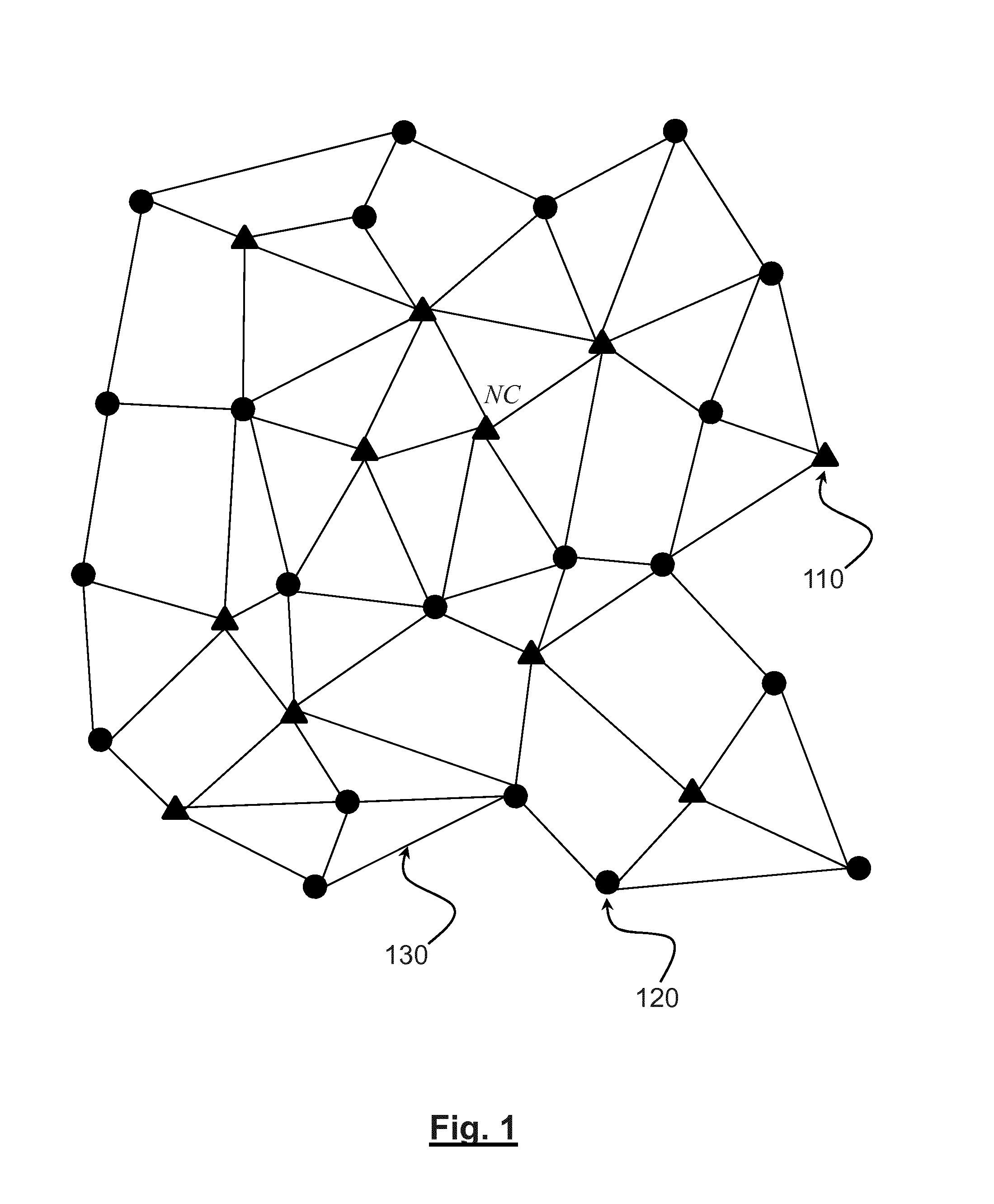
[0044]The node positioning algorithm is performed after the network discovery has been completed. Preferably, the nodes are grouped into clusters and the node positioning algorithm is carried out individually on each cluster. Without loss of generality, we will assume in the following that the network contains only one cluster.

[0045]At step 310, each regular node i of the network measures the respective received signal strengths (RSSs) of the signals it respectively receives from its neighbors j.

[0046]At step 320, the propagation channels linking neighboring nodes are classified into different channel categories. For example, the channels can be classified into line of sight (LOS) and non line of sight (NLOS) categories as explained further below. Preferably, the channels are classified into three categories: LOS, NLOS and NLOS2 as defined above. Additional categories may be envisaged wi...

second embodiment

[0077]FIG. 5 illustrates a node positioning algorithm according to the invention.

[0078]It is assumed in this embodiment that the channels are classified according to the statistics of their CIRs as in the first variant described above, or that the channel classification is provided by a distinct and independent classifier.

[0079]Contrary to the first embodiment in which path loss parameters αLOS, αNLOS, αNLOS2, PL0,LOS, PL0,NLOS2, σLOS2, σNLOS2, σNLOS22 were assumed to be known a priori from the channel model, the present embodiment performs a blind estimation of at least some of these parameters, as explained hereinafter.

[0080]Steps 510, 520, 540, 550 are identical to steps 310, 320, 340, 340, and therefore their description will be omitted.

[0081]At step 530, the path loss parameters of LOS, NLOS and NLOS2 are initialized at predetermined values.

[0082]The distances estimates, {tilde over (d)}ij, are then first calculated in step 540 on basis of these initial values.

[0083]After the p...

third embodiment

[0088]FIG. 6 illustrates a node positioning algorithm according to the invention.

[0089]The third embodiment differs from the first in that the effects of sensitivity limitation of the receivers are now taken into account.

[0090]More specifically, steps 610 to 640 are identical to steps 310 to 340, respectively.

[0091]At step 645, however, the systematic biases on the distance estimates and the change of the distance variance terms, induced by the sensitivity limitation, are corrected.

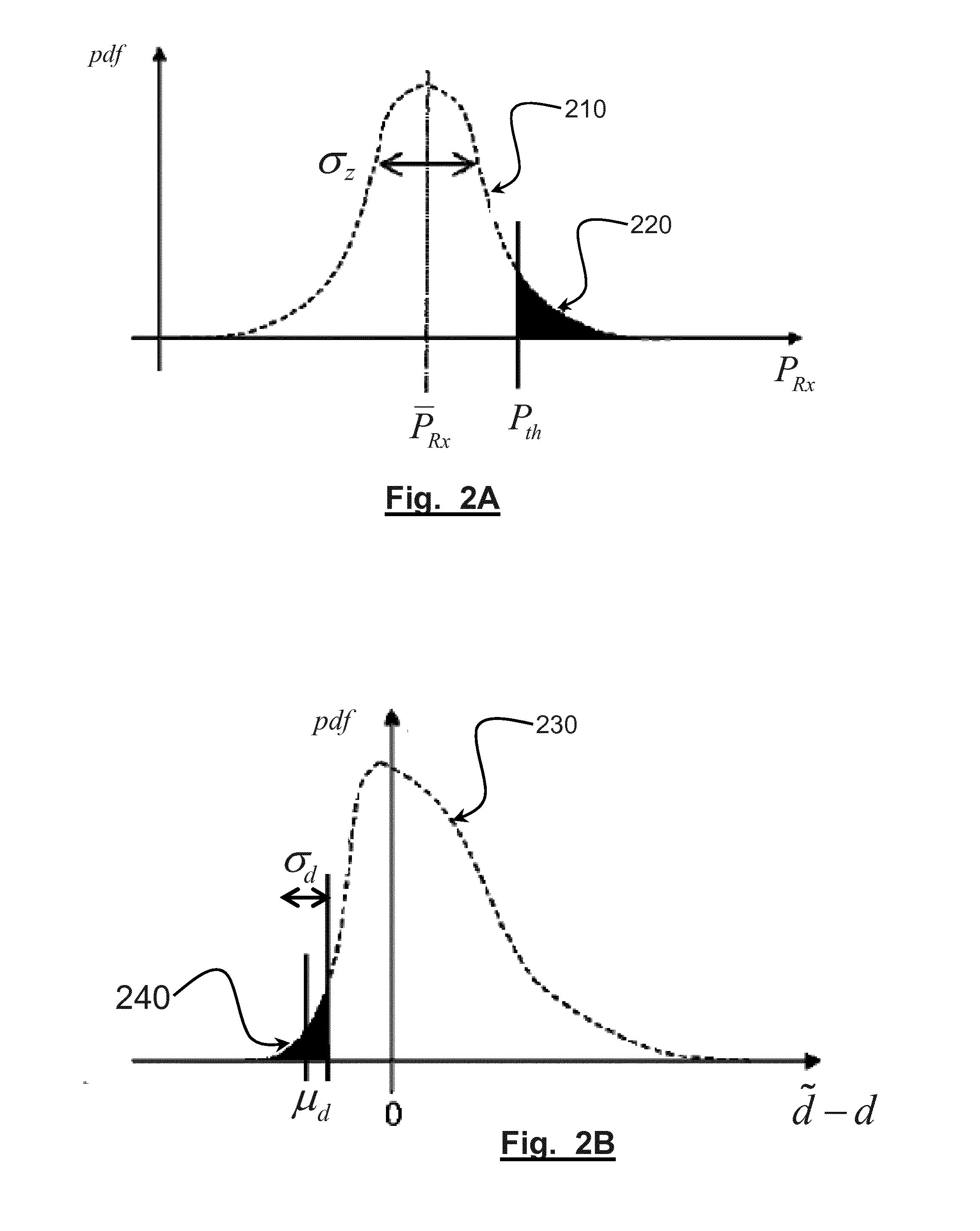
[0092]Assuming the median estimator is used, it is recalled (see expression (5)) that, for a perfect receiver with infinite sensitivity (i.e. infinite detection threshold in dBm), the distance d can be estimated from received signal strength PRx:

{tilde over (d)}=exp(M) where

M=([PTx+GRx+GTx-PRx]-PL0)log(10)10α+log(d0)

[0093]For a real receiver having finite detection threshold Pth, only the detected received power below this threshold can be taken into account into the further ranging and positioning calcul...


PUM


Abstract

A method for positioning a collection of nodes within a wireless sensor network in which each node measures Respective Strength of Signals (RSSs), from its neighboring nodes, and channels linking regular nodes and its neighboring nodes are classified into different categories and are allocated path loss parameters accordingly. Distances separating each regular node from each of its neighboring nodes, and respective variances thereof, are estimated on the basis of the measured RSSs and the allocated path loss parameters. The positions of the regular nodes are then estimated by Weighted Least Square, optimization where the distances to be matched and the variances used for the weighting are those previously estimated.

Description

TECHNICAL FIELD[0001]The present application pertains to the field of wireless networks, more particularly to Wireless Sensor Networks (WSNs). It relates to a method for positioning nodes in such networks.PRIOR ART[0002]Wireless Sensor Networks (WSNs) can be applied to various areas such as military affairs, commerce, medical care, environment monitoring and have been a subject of intensive research over the last few years. In a wireless sensor network (WSN), data collected by the nodes (sensors) are typically collected and processed by one or more controlling nodes. In many applications (e.g. environment monitoring), processing of the data cannot be performed without knowing the respective positions of the nodes these data are collected from.[0003]Many positioning algorithms have been proposed in the prior art to determine the location of nodes in a WSN. These algorithms generally assume that the position of certain nodes, also called anchor nodes or landmarks, have an a priori kno...

Claims


Application Information

Patent Timeline
Patent Type & Authority Applications(United States)
IPC IPC(8): H04W4/02G01S5/02G01S5/14
CPCH04W4/02G01S5/0289H04W84/18G01S5/0278H04W64/003H04W64/00
Inventor DENIS, BENOITOUVRY, LAURENT
Owner COMMISSARIAT A LENERGIE ATOMIQUE ET AUX ENERGIES ALTERNATIVES
Why Eureka
Try Eureka