Implementing automated memory address recording in constrained random test generation for verification of processor hardware designs

a technology of memory address and random test, applied in the field of data processing, can solve the problems of increasing design complexity and requiring an exponential increase in test complexity, and limiting the information about past events that is known, and achieve the effect of negative effects

Inactive Publication Date: 2014-09-11
IBM CORP
View PDF1 Cites 3 Cited by
  • Summary
  • Abstract
  • Description
  • Claims
  • Application Information

AI Technical Summary

Benefits of technology

[0009]Principal aspects of the present invention are to provide a method and apparatus for implementing automated memory address recording in constrained random test generation for verification of processor hardware designs. Other important aspects of the present invention are to provide such method and apparatus substantially without negative effects and that overcome many of the disadvantages of prior art arrangements.
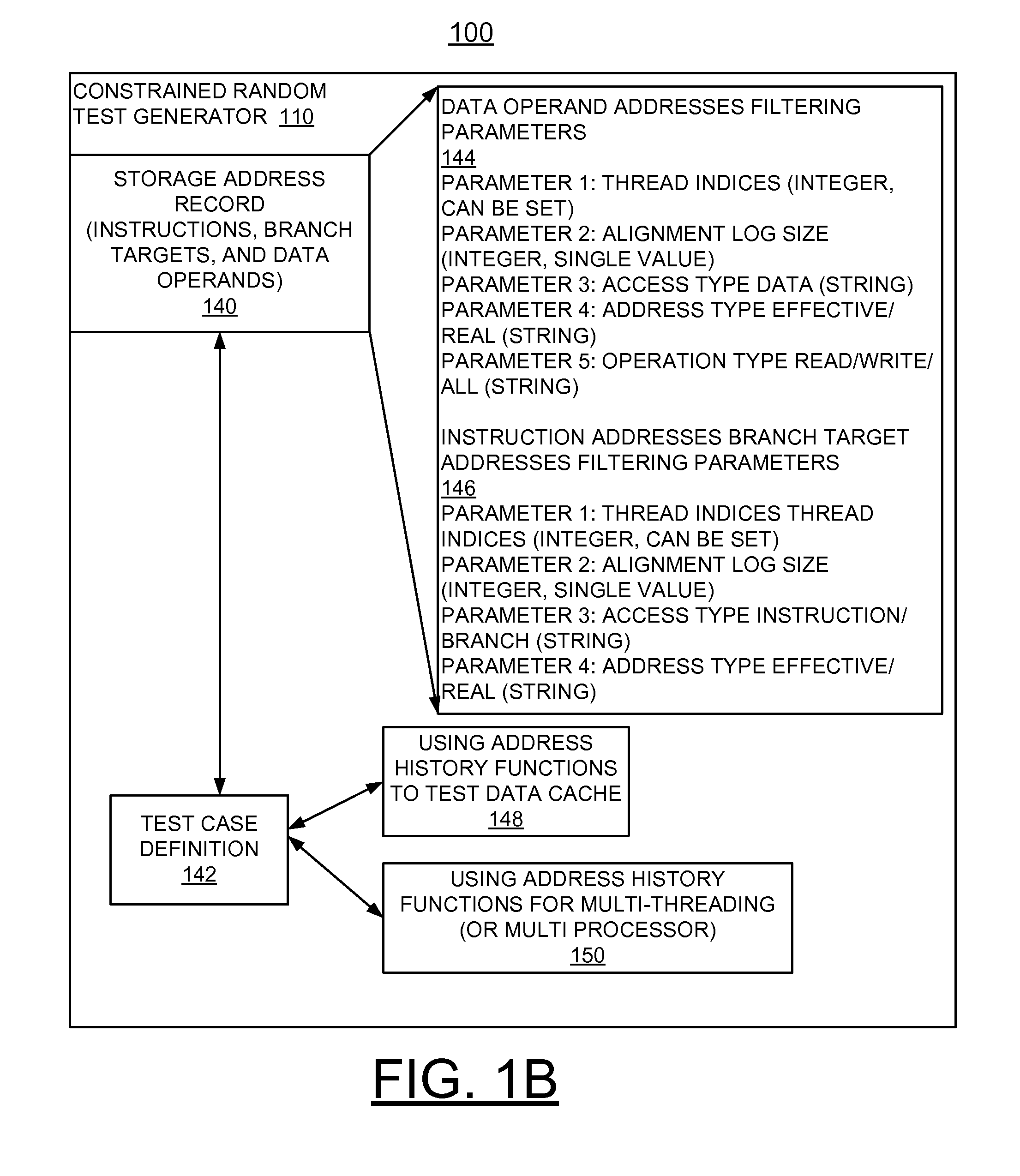
[0010]In brief, a method and apparatus are provided for implementing automated memory address recording in constrained random test generation for verification of processor hardware designs. A test generation program includes a built in feature to keep track of storage addresses used and to make the addresses available to the test definition. This built in feature of a constrained random test generator allows storage addresses used in the past to be accessed by the current instruction generation eliminating the requirement of deliberately establishing target addresses first. This allows separate test events to interact with the same storage addresses without having to write a special test.

Problems solved by technology

Such information about past events that is known is limited to the current state of the design being tested.
Increasing design complexity requires an exponential increase in test complexity to ensure that any two or more features of a processor design architecture or micro-architecture interact as expected and do not interfere with any other feature.

Method used


Image

  • Implementing automated memory address recording in constrained random test generation for verification of processor hardware designs
  • Implementing automated memory address recording in constrained random test generation for verification of processor hardware designs
  • Implementing automated memory address recording in constrained random test generation for verification of processor hardware designs

Examples


Embodiment Construction

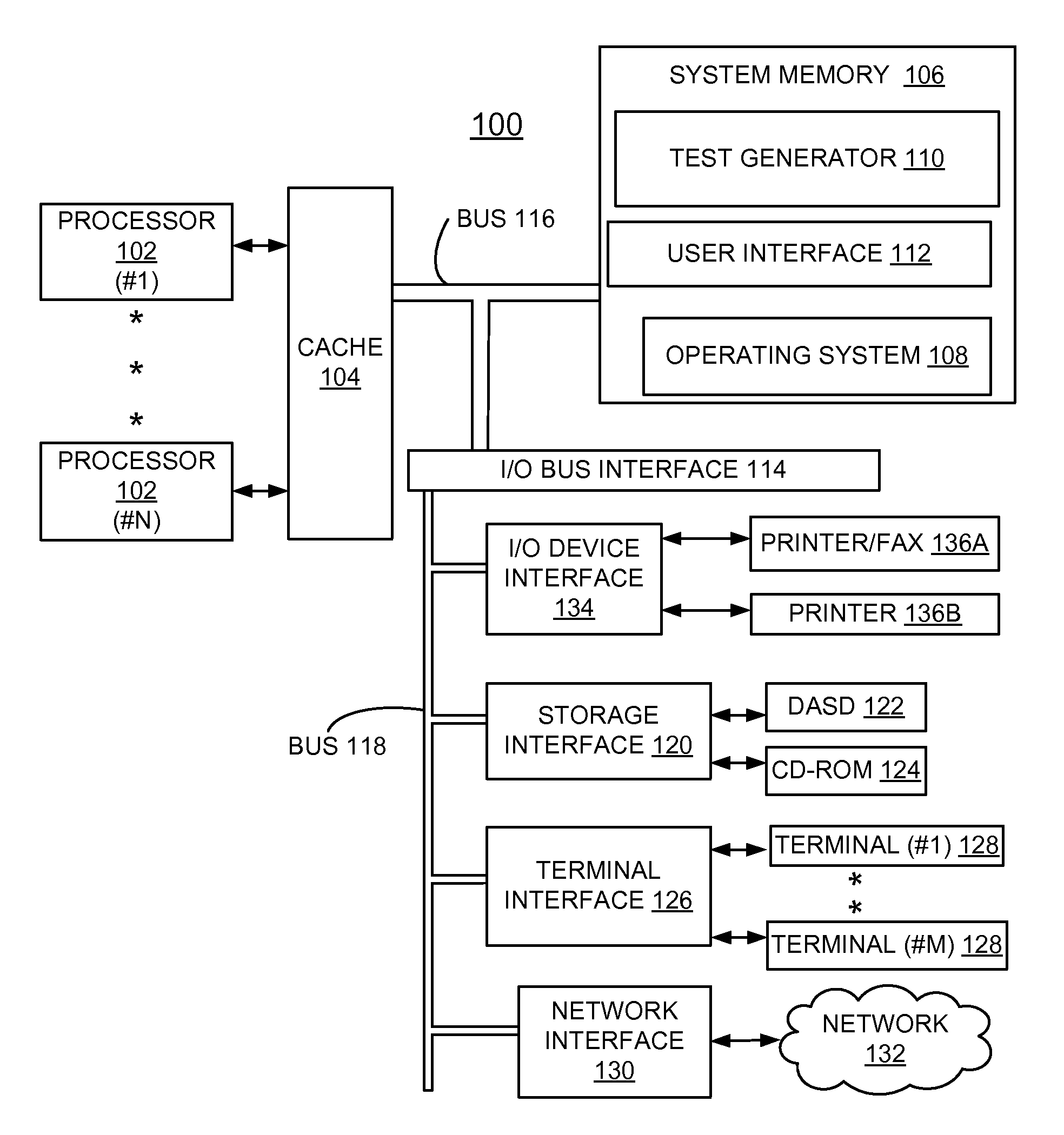
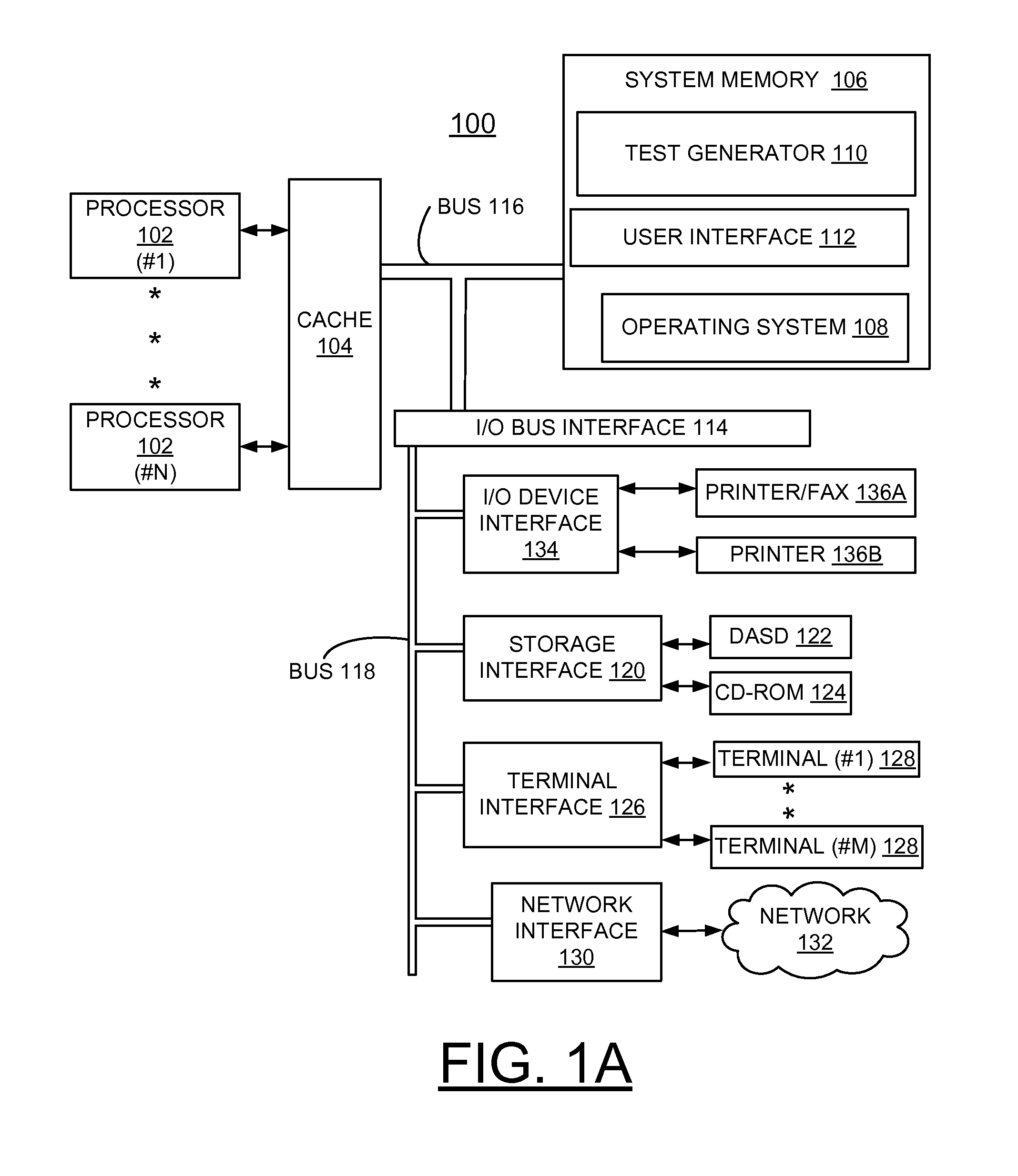
[0023]In the following detailed description of embodiments of the invention, reference is made to the accompanying drawings, which illustrate example embodiments by which the invention may be practiced. It is to be understood that other embodiments may be utilized and structural changes may be made without departing from the scope of the invention.

[0024]The terminology used herein is for the purpose of describing particular embodiments only and is not intended to be limiting of the invention. As used herein, the singular forms “a”, “an” and “the” are intended to include the plural forms as well, unless the context clearly indicates otherwise. It will be further understood that the terms “comprises” and / or “comprising,” when used in this specification, specify the presence of stated features, integers, steps, operations, elements, and / or components, but do not preclude the presence or addition of one or more other features, integers, steps, operations, elements, components, and / or gr...


PUM


Abstract

A method and apparatus are provided for implementing automated memory address recording in constrained random test generation for verification of processor hardware designs. A test generation program includes a built in feature to keep track of storage addresses used and to make the addresses available to the test definition. This built in feature of a constrained random test generator allows storage addresses used in the past to be accessed by the current instruction generation eliminating the requirement of deliberately establishing target addresses first. This allows separate test events to interact with the same storage addresses without having to write a special test.

Description

FIELD OF THE INVENTION[0001]The present invention relates generally to the data processing field, and more particularly, relates to method and apparatus for implementing automated memory address recording in constrained random test generation for verification of processor hardware designs.DESCRIPTION OF THE RELATED ART[0002]Processor pre-silicon functional verification is typically accomplished using test definitions with an automated test case generation tool, such as IBM Genesys Pro Test Program Generator which produces a sequence of assembly level instructions. These test definitions are typically produced by engineers to exercise specific architectural and micro-architectural features of the processor.[0003]U.S. Pat. No. 6,006,028 to Aharon et al., issued Dec. 21, 1999 and assigned to the present assignee discloses an architecture-independent test program generator for producing test programs for checking the operation of a hardware processor design comprises means for storing d...

Claims


Application Information

Patent Timeline
Patent Type & Authority Applications(United States)
IPC IPC(8): G06F11/00
CPCG06F11/00G06F11/22G06F11/263
Inventor ATHERTON, CRAIG T.FEDIDA, AVISHAIHENDRICKSON, OLAF K.HERSHKOVITZ, OZ
Owner IBM CORP
Why Eureka
Try Eureka