Clip on Reel Tine

a clip and reel technology, applied in the field of harvesting machines, can solve the problems of difficult to find an appropriate standard size screw, difficult to tighten the screw, and difficulty in fixing the screw, so as to prevent accidental unlocking of the clip, quick and easy installation or removal

Inactive Publication Date: 2014-09-18
AGCO CORP
View PDF5 Cites 17 Cited by
  • Summary
  • Abstract
  • Description
  • Claims
  • Application Information

AI Technical Summary

Benefits of technology

[0004]The present invention provides a tine of at least predominantly synthetic resinous material that can be quickly and easily installed on or removed from the reel without the use of auxiliary threaded fasteners such as screws or the like. In one form of the invention the tine has a generally C-shaped mounting base that receives and embraces the backside of the reel support member, while a generally C-shaped, oppositely oriented clip receives and embraces the front side of the support member. One end of the clip is attached to the base of the tine in such a manner that the clip can swing or flex toward and away from the base, while the opposite end of the clip is provided with suitable locking structure that releasably engages and interlocks with corresponding structure on the mounting base. A guard on the mounting base overlies and protects the locking end of the clip when the clip is securely locked so as to prevent accidental unlocking of the clip during field operations as crop materials and other residue might otherwise tend to force the clip open.

Problems solved by technology

However, in many instances, such plastic tines are still attached to their support members using metal fasteners such as screws.
Fastening tines to the reel using screws can take considerable time and effort.
Moreover, it may be difficult to find an appropriate standard size screw due to the substantial length and relatively small diameter required for the screw.
Another problem is under or over tightening the screw during installation.
And there is always the possibility of breaking the tine during the installation efforts.

Method used


Image

  • Clip on Reel Tine
  • Clip on Reel Tine
  • Clip on Reel Tine

Examples


Embodiment Construction

[0016]The present invention is susceptible of embodiment in many different forms. While the drawings illustrate, and the specification describes, certain preferred embodiments of the invention, it is to be understood that such disclosure is by way of example only. There is no intent to limit the principles of the present invention to the particular disclosed embodiments. Directional references such as “left” and “right” in this specification are given as if the machine were being viewed from the rear looking forwardly.

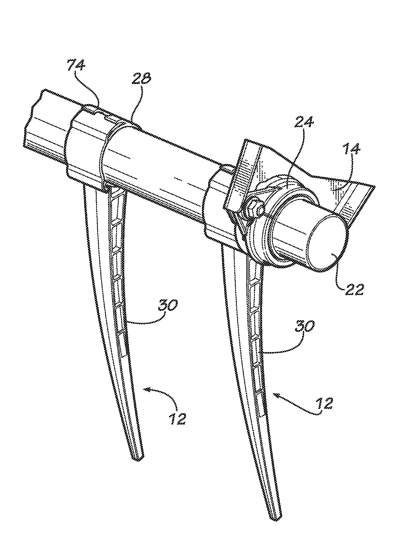
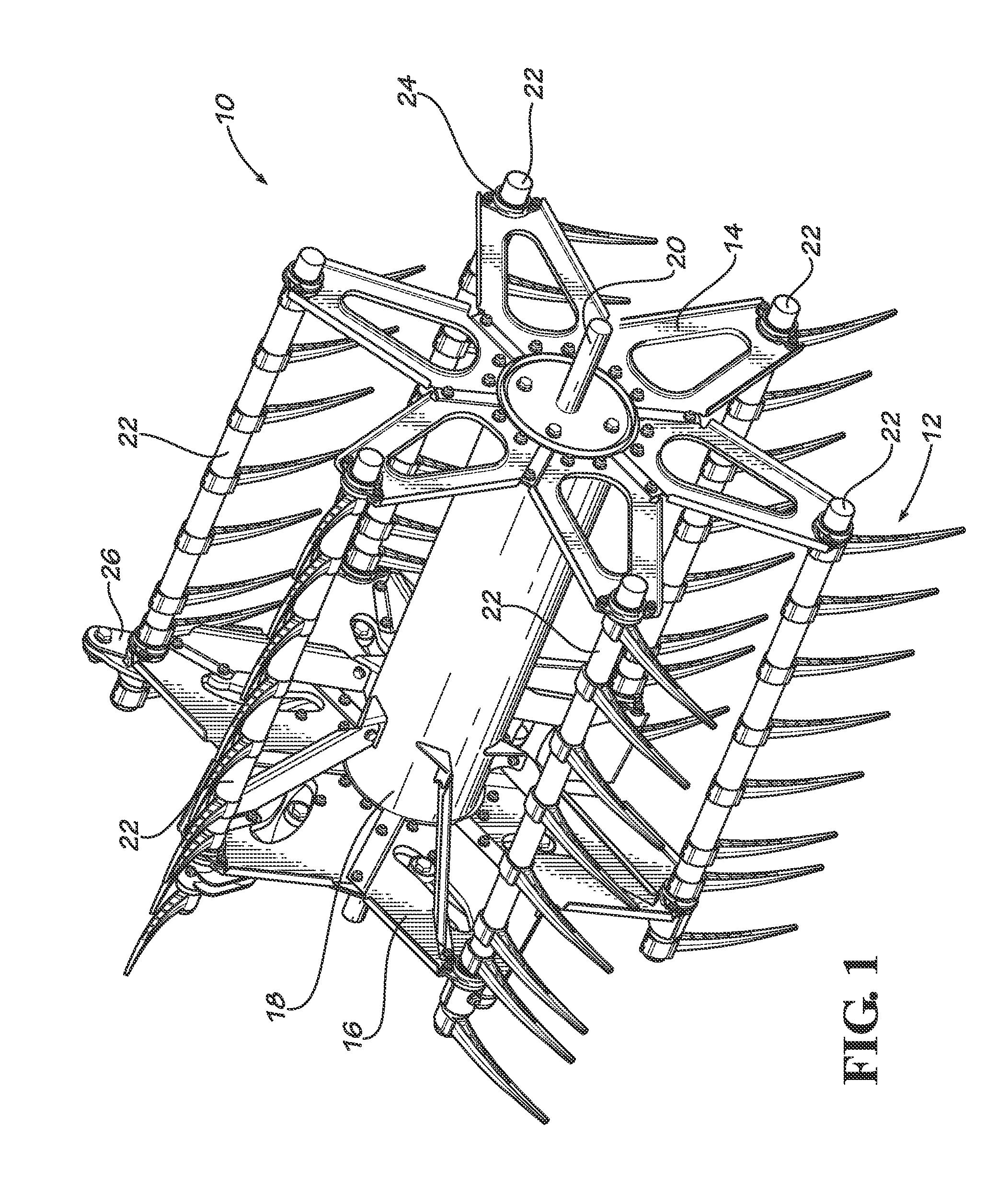
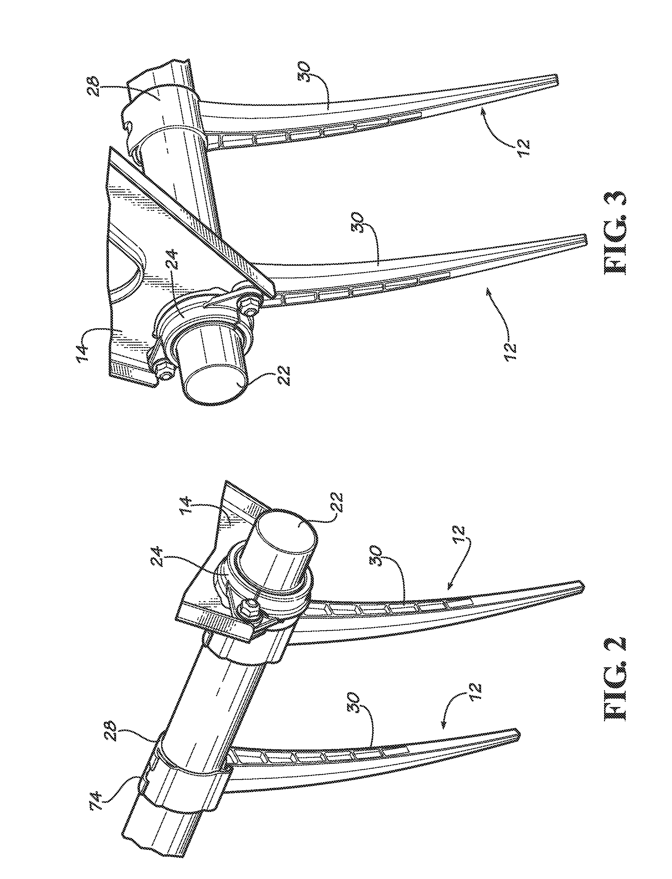
[0017]FIG. 1 shows a harvesting reel 10 of typical construction, with the exception of the tines 12 that are constructed in accordance with the principles of the present invention. Reel 10 has a pair of large, star-shaped and longitudinally spaced apart plates 14 and 16 at opposite ends of the reel, as well as a center, cylindrical tube 18 that interconnects plates 14 and 16 in concentric relationship therewith. Plates 14, 16 are secured to central tube 18 for rotation...


PUM


Abstract

A plastic tine for mounting on a support tube of a harvester reel has a generally C-shaped mounting base that snaps onto the backside of the tube and an elongated finger that projects outwardly and normally downwardly from the mounting base. A generally C-shaped clip, oriented reversely to the mounting base, partially surrounds the front side of the support tube and is connected to one leg of the mounting base in such a manner that a free end of the clip can be swung toward and away from a corresponding opposite leg of the mounting base. Interlocking structure on the free end of the clip and corresponding distal end of the mounting base retains the clip in place against the front side of the support tube when the clip is fully installed. A special guard protectively overlies the free end of the mounting clip when it is locked to the mounting base so as to prevent accidental dislodgment by crop materials and residue during field operations. Provision is made for attachment of the tine to the tube by a threaded fastener in case the clip is dislodged or unavailable in the field. Alternative embodiments include an integral one-piece construction wherein the clip is integral with the rest of the tine and a separate two-part construction wherein the clip is a separate piece attachable to the rest of the tine.

Description

TECHNICAL FIELD[0001]The present invention relates to the field of harvesting machines and, more particularly, to the tines employed on the crop gathering reels of such machines.BACKGROUND AND SUMMARY[0002]The crop gathering reels of harvesting machines are typically provided with pointed tines that engage and rake standing crop material rearwardly into the sickle or other cut off mechanism of the machine as the reel rotates and the machine advances through the field. Such tines are usually attached to transverse support members that extend along the length of the reel and oscillate about their longitudinal axes during reel rotation to place the tines in their optimum angle or attitudes as they sweep through the crop.[0003]It is known in the art to make such tines entirely, or almost entirely, out of synthetic resinous material. However, in many instances, such plastic tines are still attached to their support members using metal fasteners such as screws. Fastening tines to the reel...

Claims


Application Information

Patent Timeline
Patent Type & Authority Applications(United States)
IPC IPC(8): A01D80/02
CPCA01D80/02
Inventor MCGEHEE, GREG S.JOST, DUSTINBOLLINGER, SHANE
Owner AGCO CORP
Why Eureka
Try Eureka