Stand-Alone Solar Power Charger Directly Coupling to Portable Electronic Devices

a solar power charger and portable electronic device technology, applied in the direction of photovoltaic supports, pv power plants, semiconductor devices, etc., can solve the problems of increasing the overall cost of the pv system, ancillary equipment can be expensive, and the power generated by pv arrays and equipment is generally more expensive than equivalent power from other sources, so as to achieve convenient replacement, shorten the working life, and improve the effect of service li

Inactive Publication Date: 2014-09-18
SUNSTREAM TECH INC
View PDF4 Cites 21 Cited by
  • Summary
  • Abstract
  • Description
  • Claims
  • Application Information

AI Technical Summary

Benefits of technology

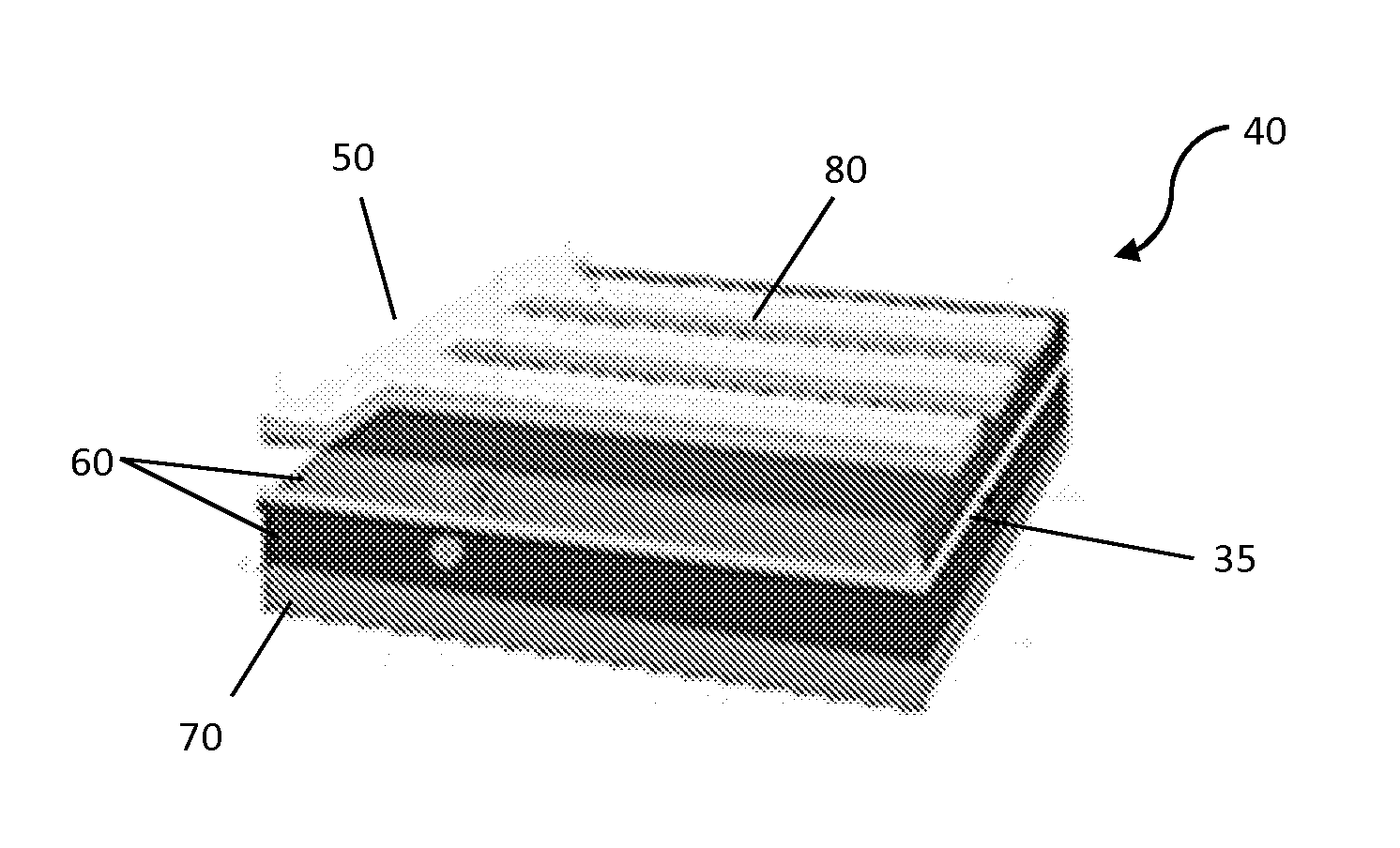
[0012]In various embodiments, a personal solar system can be designed and manufactured such that it can include easily replaceable “elements” for replacing components of the system that are likely to fail and/or become damaged during the lifetime of the system. For example, the system may be designed to include a replaceable junction box and/or junction box components. The replaceability of such components may be particularly desirous in a PV system that may have a working life of over 25 years, while various other components of the system, such as the junction box and/or female USB connector, may have a significantly shorter working life, such as 5 years or less. Unlike standard systems that require disposal of a system after breakage of a critical component, the present system allows the user to quickly, easily and inexpensively extend the useful life of the personal solar system well beyond the useful life of typical portable PV systems. In various embodiments, the user can access and replace a variety of broken components or other elements of the system, as well as modify or adapt existing components to particul

Problems solved by technology

The power generated by PV arrays and equipment is generally more expensive than equivalent power from other sources due to the inclusion of auxiliary electrical systems.
Moreover, the numerous ancillary systems and/or components necessary for use with typical PV systems impart significant additional disadvantages to such systems, which can include: (1) the ancillary equipment requires power and generates additional inefficiencies, which can reduce/de-rate and/or otherwise impact the useful power generated by the system for use by the consumer; (2) ancillary equipment can be expensive, and typically adds significant expense to the overall cost of the PV system; (3) ancillary equipment typically converts or generates a ma

Method used


Image

  • Stand-Alone Solar Power Charger Directly Coupling to Portable Electronic Devices
  • Stand-Alone Solar Power Charger Directly Coupling to Portable Electronic Devices
  • Stand-Alone Solar Power Charger Directly Coupling to Portable Electronic Devices

Examples


Embodiment Construction

[0075]The following description is presented to enable any person skilled in the art to make and use the invention. Various modifications to the embodiments described will be readily apparent to those skilled in the art, and the generic principles defined herein can be applied to other embodiments and applications without departing from the spirit and scope of the present invention as defined by the appended claims. Thus, the present invention is not intended to be limited to the embodiments shown, but is to be accorded the widest scope consistent with the principles and features disclose herein. To the extent necessary to achieve a complete understanding of the invention disclosed, the specification and drawings of all issued patents, patent publications, and patent applications cited in this application are incorporated herein by reference.

[0076]Traditional Solar Cell Manufacturing

[0077]There are a wide variety of methods to manufacture PV cells. In one exemplary description of so...


PUM


Abstract

A stand-alone solar power charger that may configured for direct coupling to a plurality of portable electronic devices. The solar power charger is particularized to power and/or charge an intended portable device or a set of intended portable devices having direct current (DC) load requirements. The solar power charger discharges energy without the use of an internal battery or ancillary electronic circuit boards, and facilitates “fast” charging modes. More specifically, the solar power charger incorporates a variety of features that make the design rugged, compact, waterproof, and durable.

Description

RELATED APPLICATIONS[0001]This application claims the benefit of U.S. Provisional Patent Application Ser. No. 61 / 644,432, entitled “Photovoltaic Solar Module with a Junction Box that Possesses a USB port(s) which are Replaceable,” filed May 9, 2012, from which priority is claimed under 35 U.S.C. 119, and the disclosure of which is hereby incorporated herein by reference in its entirety.TECHNICAL FIELD[0002]The present invention relates to an improved personal solar cell recharging apparatus and system particularized for a desired loading environment of an intended device, and having an inexpensive, portable, and ruggedized construction. More specifically, methods, systems, and devices are disclosed for optimizing a solar array construction that requires no electronic power conditioning, is durable, is inexpensive, is portable, has a low cost of manufacturing, and may desirably provide for replaceable component parts such as USB junction boxes and USB connectors, to directly recharge...

Claims


Application Information

Patent Timeline
IPC IPC(8): H01L31/042
CPCH02S20/00H02J7/0042H02J7/35H01L31/02H01L31/0201H01L31/02013H01L31/048H02S30/10H02S40/22H02S40/34Y02E10/52H02S10/40H01L31/0504
Inventor ANDERSON, JOHN AUGUSTUS
Owner SUNSTREAM TECH INC
Why Eureka
Try Eureka