Brake assembly for bicycles

a technology for brakes and bicycles, applied in the direction of cycle brakes, cycle equipment, etc., can solve the problem of reducing wind resistance of brake assemblies

Inactive Publication Date: 2014-09-18
KIMATEK INC
View PDF4 Cites 7 Cited by
  • Summary
  • Abstract
  • Description
  • Claims
  • Application Information

AI Technical Summary

Benefits of technology

[0010]The present invention relates to a brake assembly and comprises a base having two first connection parts and each first connection part has a first hole and a second hole. Two second connection parts extend from the underside of the base. Two arms are pivotably connected to the two second connection parts. A driving member has a driving part and a positioning portion. The driving part has two curved driving face formed on two ends thereof. The

Problems solved by technology

The brake assembly re

Method used


Image

  • Brake assembly for bicycles
  • Brake assembly for bicycles
  • Brake assembly for bicycles

Examples


second embodiment

[0040]As shown in FIGS. 9 to 14, the present invention is disclosed and two third returning members 50 are respectively located between the two pivotal portions 21 of the arms 20 and the two second connection parts 15 of the base 10. When the brake cable 13 does not apply force to the driving member 30, the two arms 20 return by the third returning members 50. By this way, the first returning member 14 can be omitted and the length of each extension section 23 can be reduced to reduce the weight and volume.

third embodiment

[0041]FIGS. 15 to 18 show the present invention, a cover 60 is mounted to the base 10 and the two arms 20. The cover 60 is connected to the base 10 by at least one connection member 61 and the cover 60 is shaped to reduce the turbulence and resistance, and protects the base 10 and the arms 20 from being accessed by rain, dust and any foreign object. The cover 60 is made by resilient material. As shown in FIG. 19, when the brake cable 13 fails to apply force to the brake assembly, the extension sections 23 of the arms 20 are pivoted and contact the cover 60 so as to help the two extension sections 23 to return.

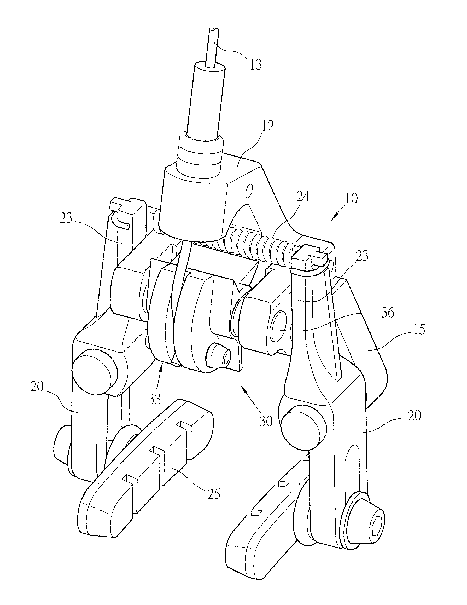
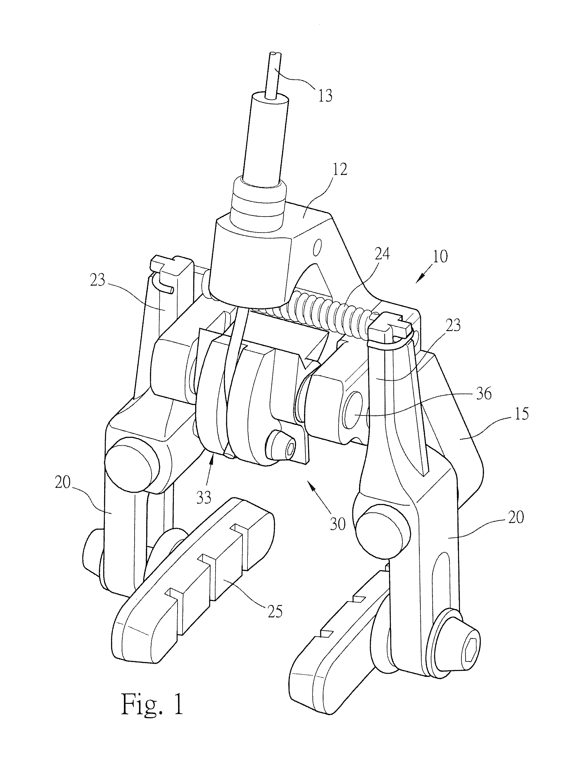
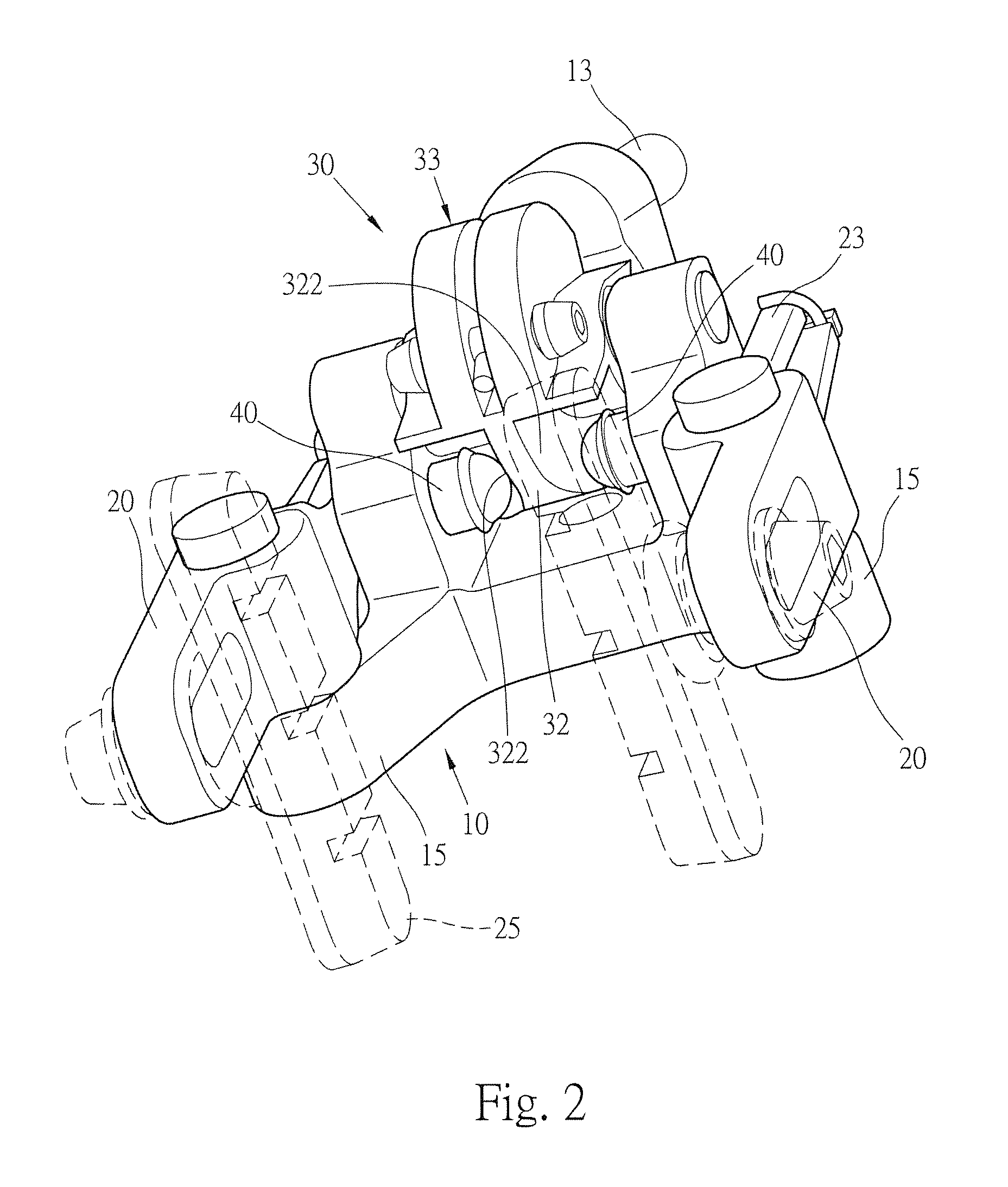
[0042]The base 10 is pivotably connected to the cam-shaped driving member 30 to which the brake cable 13 is connected. The driving part 32 is formed on outside of the driving part 32 which has two curved driving faces 322 formed on two ends thereof. Two action members 40 are respectively located between the arms 20 and the two curved driving faces 322. When the driving member 3...


PUM


Abstract

A brake assembly includes a base having two first connection parts and each first connection part has a first hole and a second hole. Two second connection parts extend from the underside of the base. Two arms are pivotably connected to the two second connection parts. A driving member has a driving part and a positioning portion. The driving part has two curved driving face formed on two ends thereof. The driving member is connected to the first hole by a rod, and a brake cable is connected to the positioning portion. The action members are respectively located in the two second holes. When the driving member is pivoted by the brake cable, the driving member pushes the action members to pivot the arms to brake the wheel. The driving member allows the force to be sent to the brake pads directly and quickly, and the brake assembly is light and compact.

Description

FIELD OF THE INVENTION[0001]The present invention relates to a brake assembly for a bicycle, and more particularly, to a driving member of the brake assembly to increase the braking efficiency. The brake assembly is light and compact.BACKGROUND OF THE INVENTION[0002]The bicycles are welcomed to people not only for transportation but also for leisure activities. Along with the time for operating the bicycles increases, the safety for the cyclists are more concerned and the brake assembly for bicycles are directly related to the safety of the cyclists.[0003]The conventional brake assembly for bicycles is connected to front fork or the seat stays, and generally comprises two arms and each arm has a brake pad connected thereto. The brake cable is connected to one side or the central portion of the arms so that the two arms are pivoted toward each other to allow the brake pads to contact the rim to stop the rim, such that the speed of the bicycle can be controlled.[0004]For the brake cab...

Claims


Application Information

Patent Timeline
IPC IPC(8): B62L1/16
CPCB62L1/16
Inventor COBB, JOHN
Owner KIMATEK INC
Why Eureka
Try Eureka