
System and method for preparing, dispensing, and curing epoxy

a technology of epoxy and dispensing method, applied in the direction of electrical programme control, instruments, program control, etc., can solve the problems of fiber optic cable connector assembly breakdown and failure, product structural failure, and product structural failur

Active Publication Date: 2014-09-18
NORTH AMERICAN INTERCONNECT
View PDF5 Cites 11 Cited by
  • Summary
  • Abstract
  • Description
  • Claims
  • Application Information

AI Technical Summary

Benefits of technology

The patent describes a computer system that can dispense epoxy by using an epoxy injector. The system receives data about the container that will receive the epoxy and calculates the amount of epoxy needed. The system then sends instructions to the epoxy injector to dispense the desired amount of epoxy. The system also has a support arm that can retract to prevent the epoxy from splashing or getting on the surface being worked on. The technical effect of this system is that it makes the dispensing of epoxy easier and more efficient, resulting in less waste and better accuracy in the amount of epoxy used.

Problems solved by technology

If not assembled properly, however, fiber optic cable connector assemblies can breakdown and fail.
Specifically, inclusion of bubbles inside a fiber optic cable / connector assembly can result in structural failure during the life of the product.
Incorrectly withdrawing the syringe from a connecter after injecting the epoxy can lead to structural failure of the product as well.
Specifically, when extracting the needle at an incorrect speed, epoxy residue may be left on the inside walls of the connector body as a result of excess epoxy migrating to the outside of the needle and then transferring to the connector wall.
Once cured, this material can break free of the connector wall and potentially contaminate the installation environment, and eventually lead to connection failure.

Method used


Image

  • System and method for preparing, dispensing, and curing epoxy
  • System and method for preparing, dispensing, and curing epoxy
  • System and method for preparing, dispensing, and curing epoxy

Examples


Embodiment Construction

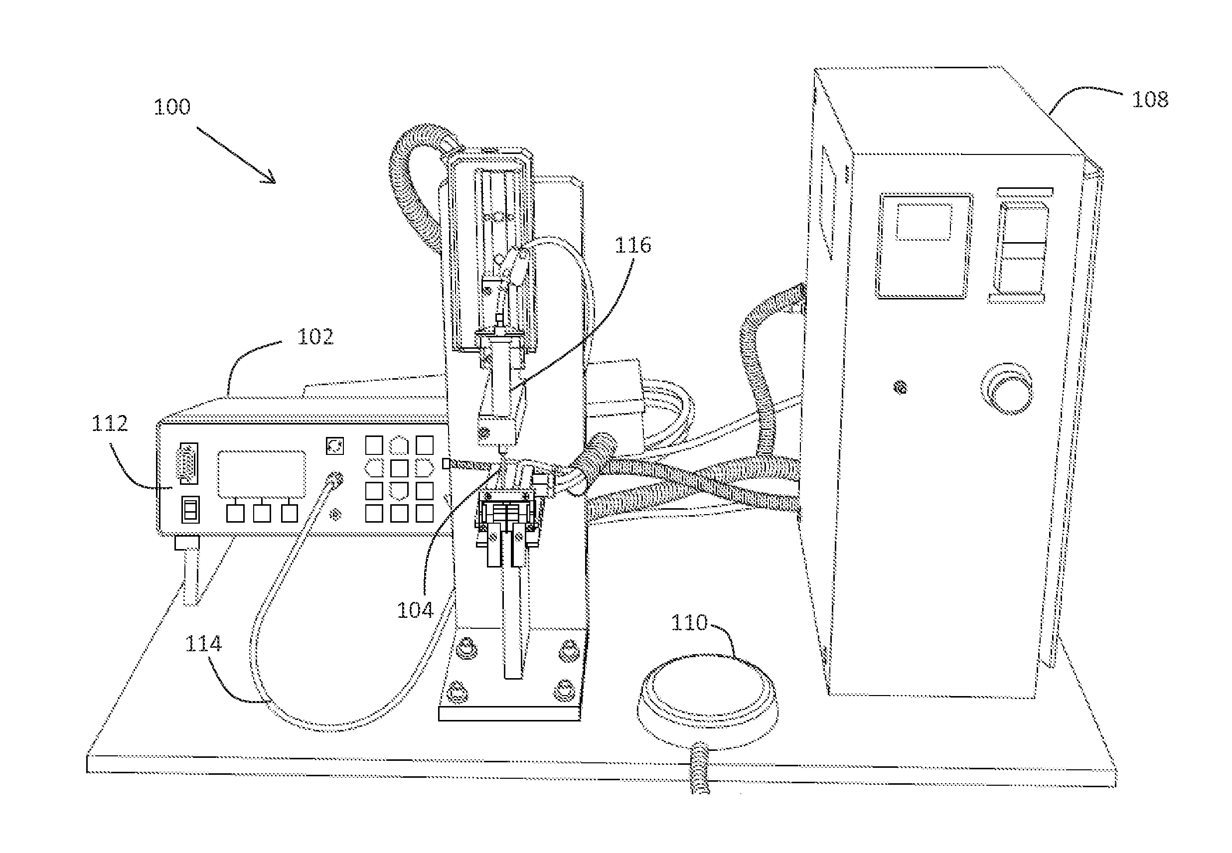
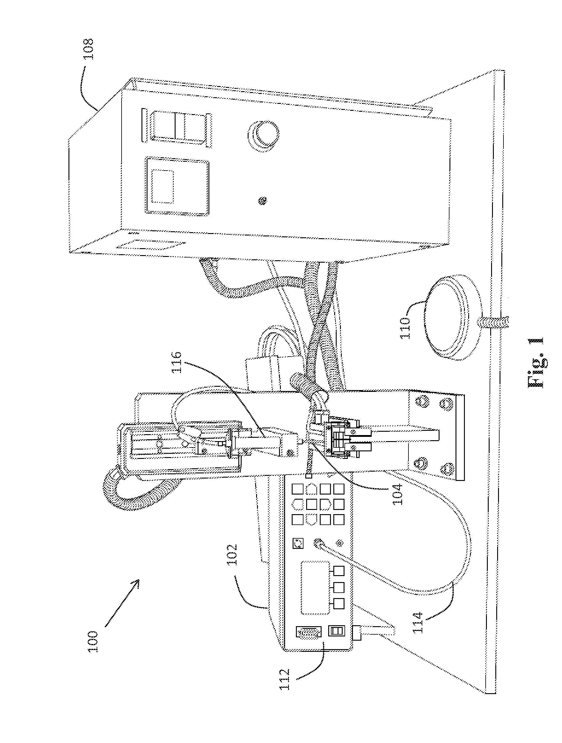
[0012]FIG. 1 illustrates an embodiment of an example system 100 for dispensing epoxy. System 100 enables an operator to inject a defined and controlled amount of epoxy into a designated area without leaving residue in or around the area. For example, system 100 may be used to inject epoxy into a cavity of a fiber optic cable connector. Eliminating residue may eliminate possibility for contamination and thereby may help prevent a fiber optic cable connector from failing structurally.

[0013]It should be understood that, although the systems and methods described herein make reference to dispensing epoxy into a cavity of a fiber optic cable connector, the systems and methods may similarly be applies to dispensing epoxy into other suitable containers or objects comprising a cavity for receiving epoxy.

[0014]System 100 includes an epoxy dispenser (or injector) 102 configured to dispense an epoxy solution. Epoxy dispenser 102 can be an Engineered Fluid Dispenser (EFD) manufactured by Nordso...


PUM

PropertyMeasurementUnit
timeaaaaaaaaaa
temperatureaaaaaaaaaa
viscosityaaaaaaaaaa

Abstract

A method for dispensing epoxy comprising the step of degassing an epoxy. The method further comprises the step of associating the epoxy with an epoxy injector comprising a dispensing end. The method further comprises the step of a computer receiving data representative of a selected container to receive the epoxy. The method further comprises the step of a computer determining a dispensing rate and a dispensing amount, based on the received data. The method further comprises the step of a computer causing the epoxy injector to dispense the determined dispensing amount of epoxy, via the dispensing end, at the determined dispensing rate. The method further comprises the step of a computer causing a dispensing arm, supporting the dispensing end, to retract the dispensing end while the epoxy injector is dispensing the epoxy. The method further comprises the step of curing the dispensed epoxy.

Description

BACKGROUND[0001]Epoxy is commonly used to assemble fiber optic cable with fiber optic connectors. Epoxy is injected into a connector using a needle or syringe. The syringe is then withdrawn and a fiber cable is inserted in the connecter. The fiber optic cable / connecter assembly is then cured. If not assembled properly, however, fiber optic cable connector assemblies can breakdown and fail. Specifically, inclusion of bubbles inside a fiber optic cable / connector assembly can result in structural failure during the life of the product.[0002]Incorrectly withdrawing the syringe from a connecter after injecting the epoxy can lead to structural failure of the product as well. Specifically, when extracting the needle at an incorrect speed, epoxy residue may be left on the inside walls of the connector body as a result of excess epoxy migrating to the outside of the needle and then transferring to the connector wall. Once cured, this material can break free of the connector wall and potentia...

Claims


Application Information

Patent Timeline
Patent Type & Authority Applications(United States)
IPC IPC(8): B05C11/10
CPCB05C11/1002B05C5/0216B05D1/26B29C65/4835B29C65/524B29C31/04B29L2011/0075B29C39/24B29K2063/00G02B6/3861G05B19/18B29B2013/005G05B2219/45238B29C66/342B29C31/06B05C11/1021B05C11/1042B29B13/00
Inventor DUINEN, KEITH VANRODRIGUEZ, MIGUELLEON, ALEJANDRO
Owner NORTH AMERICAN INTERCONNECT
Learn More