
Beverage Dispense System and Method

Inactive Publication Date: 2014-09-18
HEINEKEN UK
View PDF68 Cites 4 Cited by
  • Summary
  • Abstract
  • Description
  • Claims
  • Application Information

AI Technical Summary

Benefits of technology

The patent aims to provide a beverage dispense system that reduces microorganism growth and waste by cooling the beverage line carrying it from the cooler to the dispense font. This is achieved by enclosing the entire first beverage line portion within an insulated carrier that contains a cooling line carrying cooling medium for the beverage line. Additionally, the patent aims to prevent the accumulation of dust and other debris on the surfaces of the system, which may lead to reduced cleanliness and potentially hazardous situations. This is achieved by providing a slanting top surface, which makes it difficult for users to deposit items that may collect dust.

Problems solved by technology

If the temperature of the beverage is too high, the quality and the taste of the beverage may be impaired.
The spoiling of the beverage reduces its quality and impairs its taste which may result in increased waste if it becomes necessary to discard spoiled beverage.
Line cleaning is a time consuming task that inevitably leads to some waste of beverage and can lead to a considerable waste of beverage if it is carried out inexpertly (which is often the case).
Cooling the cellar / storage room to a lower temperature in an attempt to reduce microorganism growth is not ideal because of the extra energy that this will consume and also because many public houses / bars also store cask ales in their cellar / storage room and the quality of these cask ales will be impaired by lower temperatures.
A significant amount of beverage is wasted by being bled from valve.
Furthermore, this volume is typically drained onto the floor of the cellar / storage room which is unsightly, unhygienic (since it will be prone to microorganism growth) and a potential slipping hazard.

Method used


Image

  • Beverage Dispense System and Method
  • Beverage Dispense System and Method
  • Beverage Dispense System and Method

Examples


Embodiment Construction

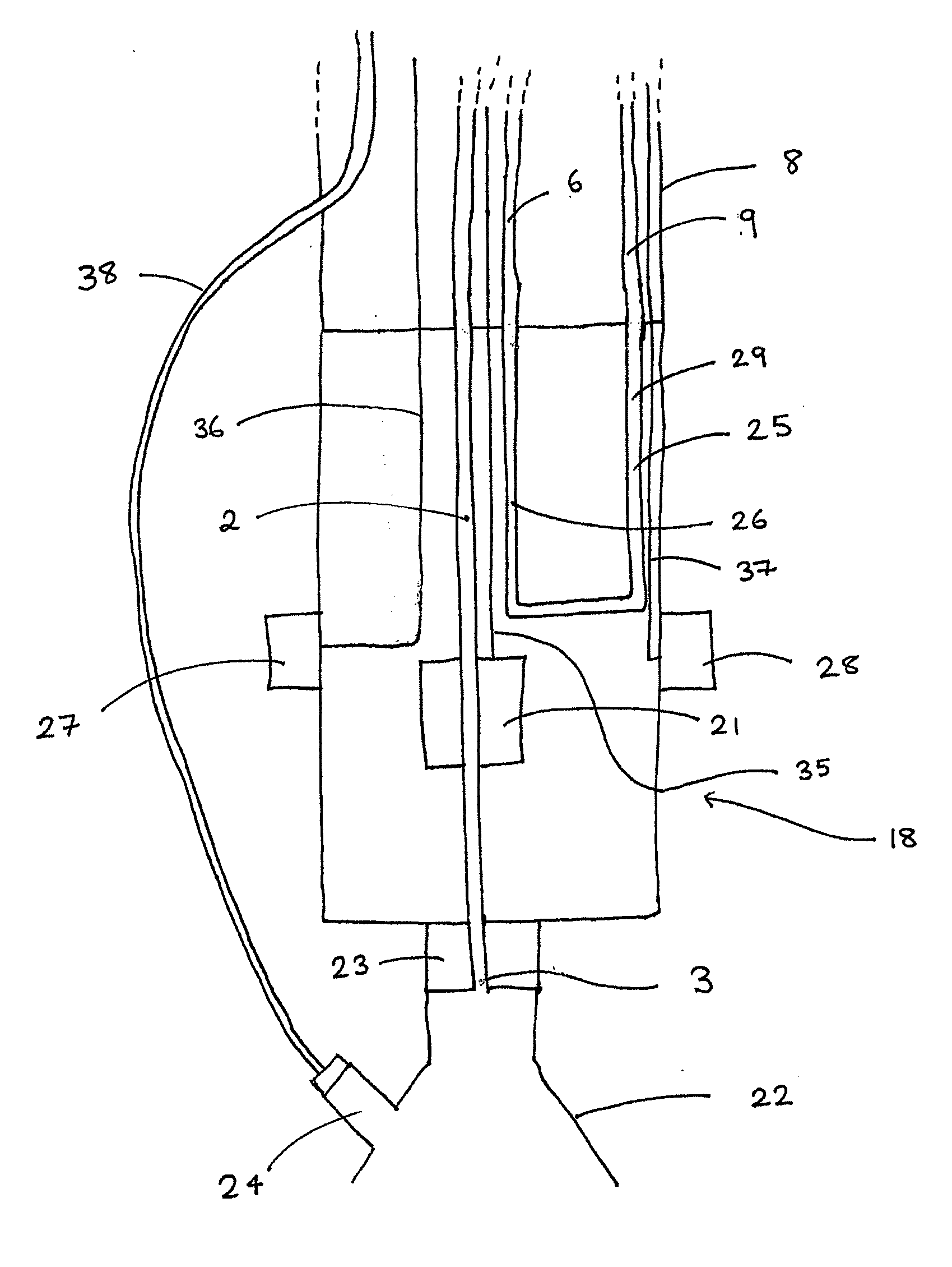
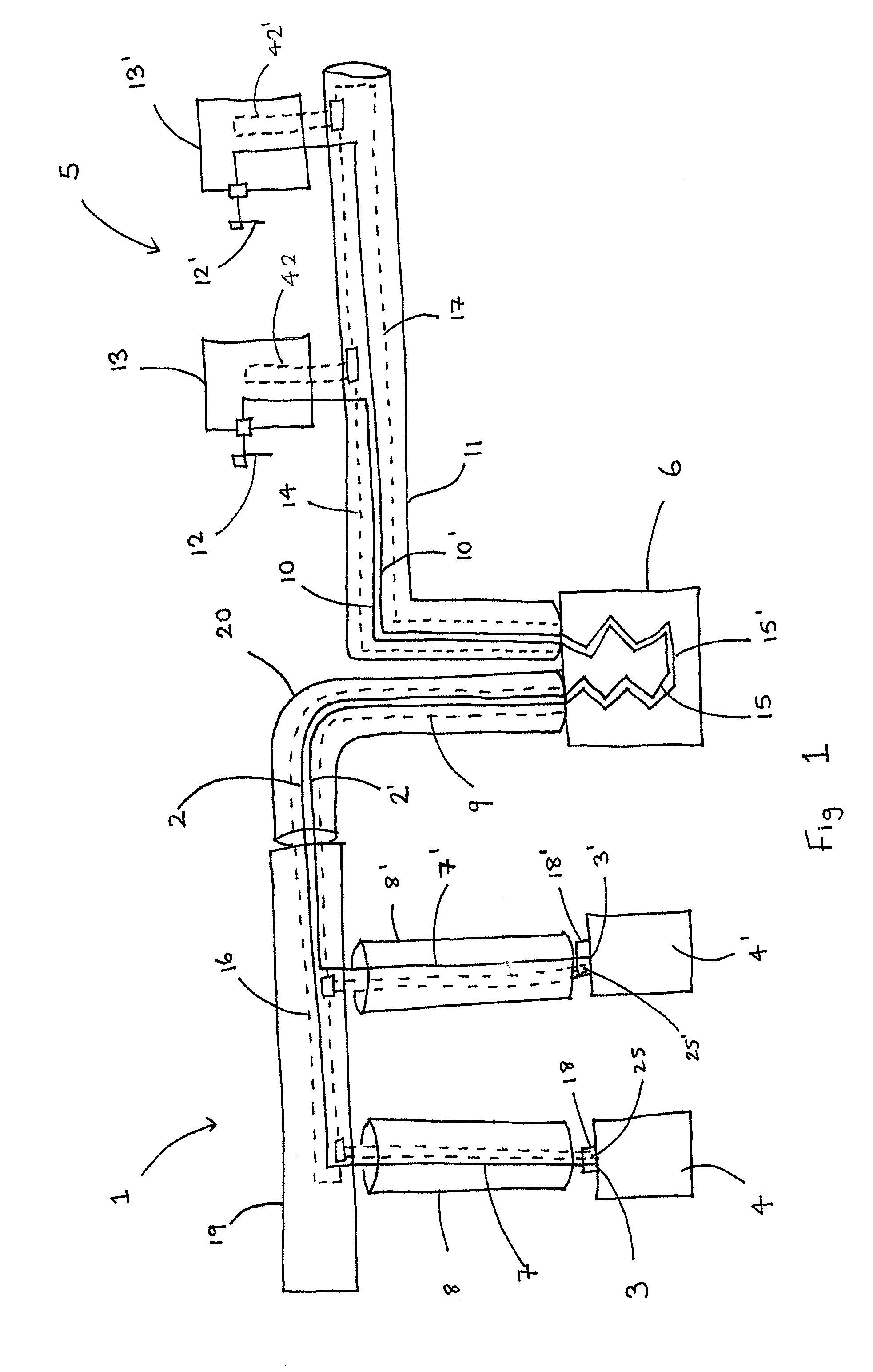
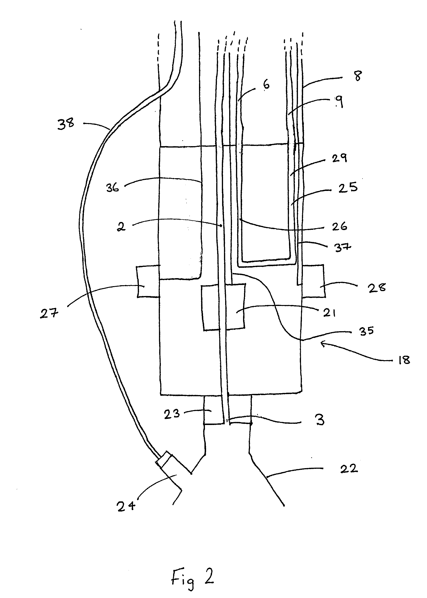
[0100]FIG. 1 shows a beverage dispense system 1 for dispensing two beverages.

[0101]The system comprises: two beverage lines 2, 2′ each having a distal end 3, 3′ connectable to a respective beverage supply 4, 4′ for transporting beverage from each beverage supply 4, 4′ to a dispensing site 5 having two dispense fonts 13, 13′ each with a respective tap 12, 12′ through which the beverage is dispensed.

[0102]The system further comprises a cooler 6 for cooling beverage. The cooler 6 is adapted to generate cooling medium. The cooler 6 comprises an ice bank and a cooling medium reservoir (not shown), the cooling medium in the cooling medium reservoir being cooled by the ice bank.

[0103]Each beverage line 2, 2′ comprises a first beverage line portion 7, 7′ extending from the respective distal end 3, 3′ to the cooler 6. Each first beverage line portion 7, 7′ extends within a first insulated carrier which is made up of a respective distal first insulated carrier portion 8, 8′ which is a python-...


PUM

PropertyMeasurementUnit
Lengthaaaaaaaaaa

Abstract

The present invention relates to beverage dispense systems and methods. The systems comprise a beverage line having a distal end connectable to a beverage supply for transporting beverage from the beverage supply to a dispense font at a dispensing site. They also include a cooler for cooling beverage. The beverage line comprises a first beverage line portion extending from the distal end to the cooler within a first insulated carrier. The first insulated carrier comprises a first cooling line for transporting cooling medium through the first insulated carrier so as to allow heat exchange between the cooling medium in the first cooling line and the beverage in the first beverage line portion.

Description

[0001]The present invention relates to beverage dispense systems and methods. In particular, the present invention relates to beverage dispense systems and methods for dispensing beverages such as lager or cider at a low temperature.BACKGROUND[0002]Many beverages including beers, lagers and ciders are beneficially served at low temperatures. If the temperature of the beverage is too high, the quality and the taste of the beverage may be impaired. In addition, recent consumer trends have increased the demand for beverages to be served at a lower temperature, for example, below 3° C. In order to meet consumer expectations, it is desirable to dispense beverages at a consistent low temperature.[0003]Systems are known for dispensing draught beverages. By “draught beverages” is meant beverages which are stored at a point remote from the point of dispensing and transferred on demand to the point of dispensing through a beverage line. Typically the transfer is achieved using a pumping mecha...

Claims


Application Information

Patent Timeline
IPC IPC(8): B67D1/08
CPCB67D1/0878B67D1/0857B67D1/0867B67D2210/00099Y10T29/49826Y10T137/7722
Inventor MERRIFIELD, CHRISBRIANT, STUARTGRAY, SIMON
Owner HEINEKEN UK
Learn More