
Terahertz time-domain spectroscopic ellipsometry system

a spectroscopic ellipsometry and time-domain technology, applied in the field of terahertz ellipsometry systems, can solve the problems of difficult application of metal technology, difficult reflected positioning of compounds, and difficult application of techniques on many materials,

Active Publication Date: 2014-09-18
THE JOHN HOPKINS UNIV SCHOOL OF MEDICINE
View PDF4 Cites 40 Cited by
  • Summary
  • Abstract
  • Description
  • Claims
  • Application Information

AI Technical Summary

Benefits of technology

The present invention is a system that uses an optical technique called terahertz time-domain spectroscopic ellipsometry to analyze samples. It includes a sample stage, a laser that sends pulses of heated radiation to the sample, and a detection system that measures the radiation that comes back from the sample. The sample stage can be rotated to change the angle between the laser and the detection system, and the detection system makes sure to always align with the laser for accurate measurements. The system measures the sample's absorption and birefringence, which provide important information about its structure and properties.

Problems solved by technology

However, transmission measurements are not possible on many materials and so far the technique has been difficult to apply to many metals, thick or highly doped semiconductors, coatings on thick substrates, substances in aqueous solution, and any otherwise opaque compound.
Moreover, an outstanding technical problem with THz-TDS continues to be the determination of absolute spectral values when performing measurements in a reflection geometry [5]-[6].
A reason why THz time-domain reflection measurements are challenging is that the time-domain technique rests on the ability to detect the relative amplitude and phase of a time-dependent electric field of a sample as compared to a reference.
For reflection based THz time-domain a simple mirror cannot easily be used as a reference because its surface would need to be positioned within a fraction of a micron in exactly the same place as the sample so that the reflected positioning is challenging.
Unfortunately the lack of sufficiently intense sources (in addition to the calibration issues we confront here) has meant that such efforts have been challenging, although synchrotron-based efforts have made some important contributions in this regard [12]-[13].
None of the proposed THz-TDSE experimental setups can provide an easy way of changing the angle of incidence without tedious work of optical / terahertz realignments.

Method used


Image

  • Terahertz time-domain spectroscopic ellipsometry system
  • Terahertz time-domain spectroscopic ellipsometry system
  • Terahertz time-domain spectroscopic ellipsometry system

Examples


examples

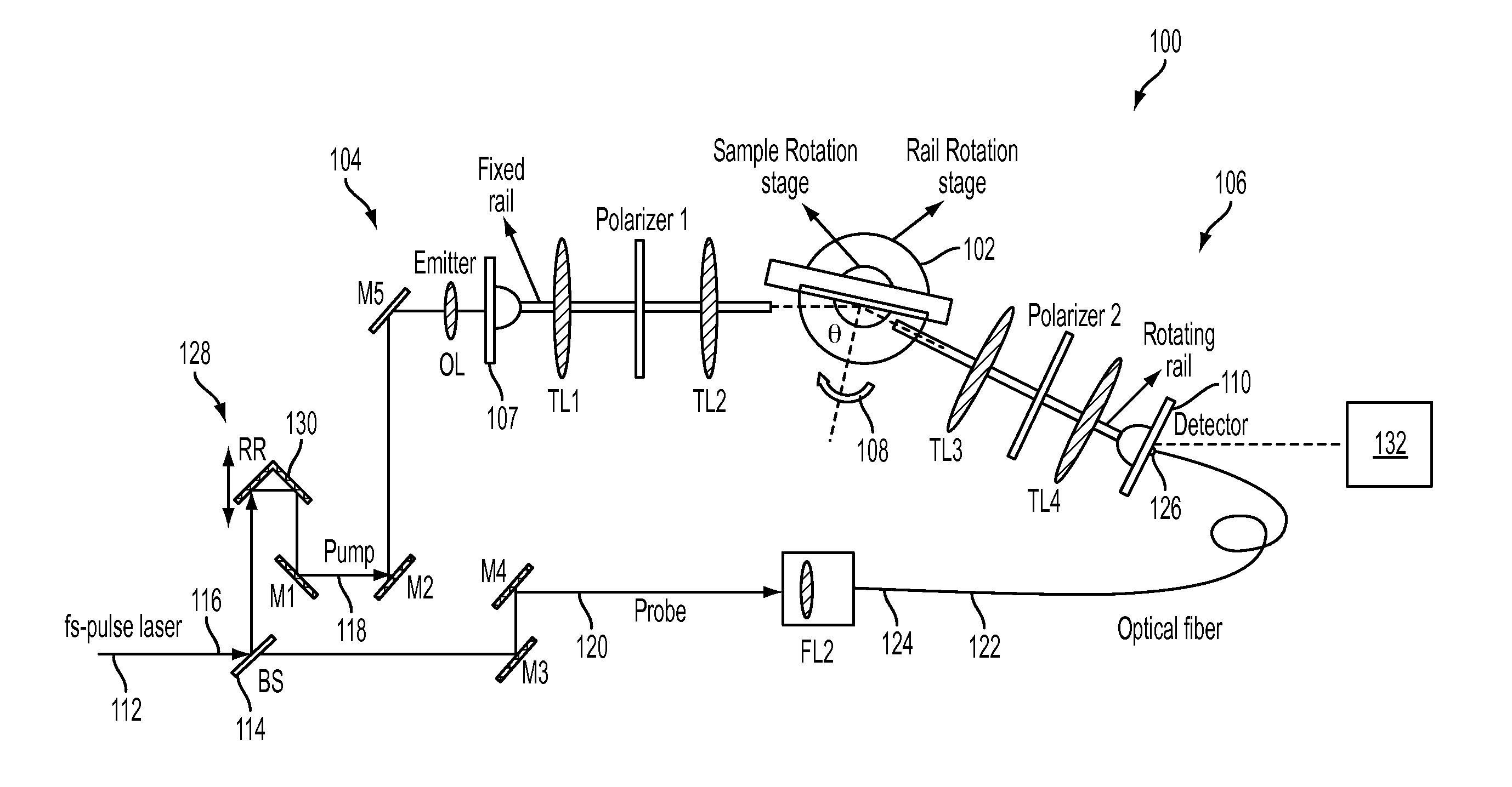
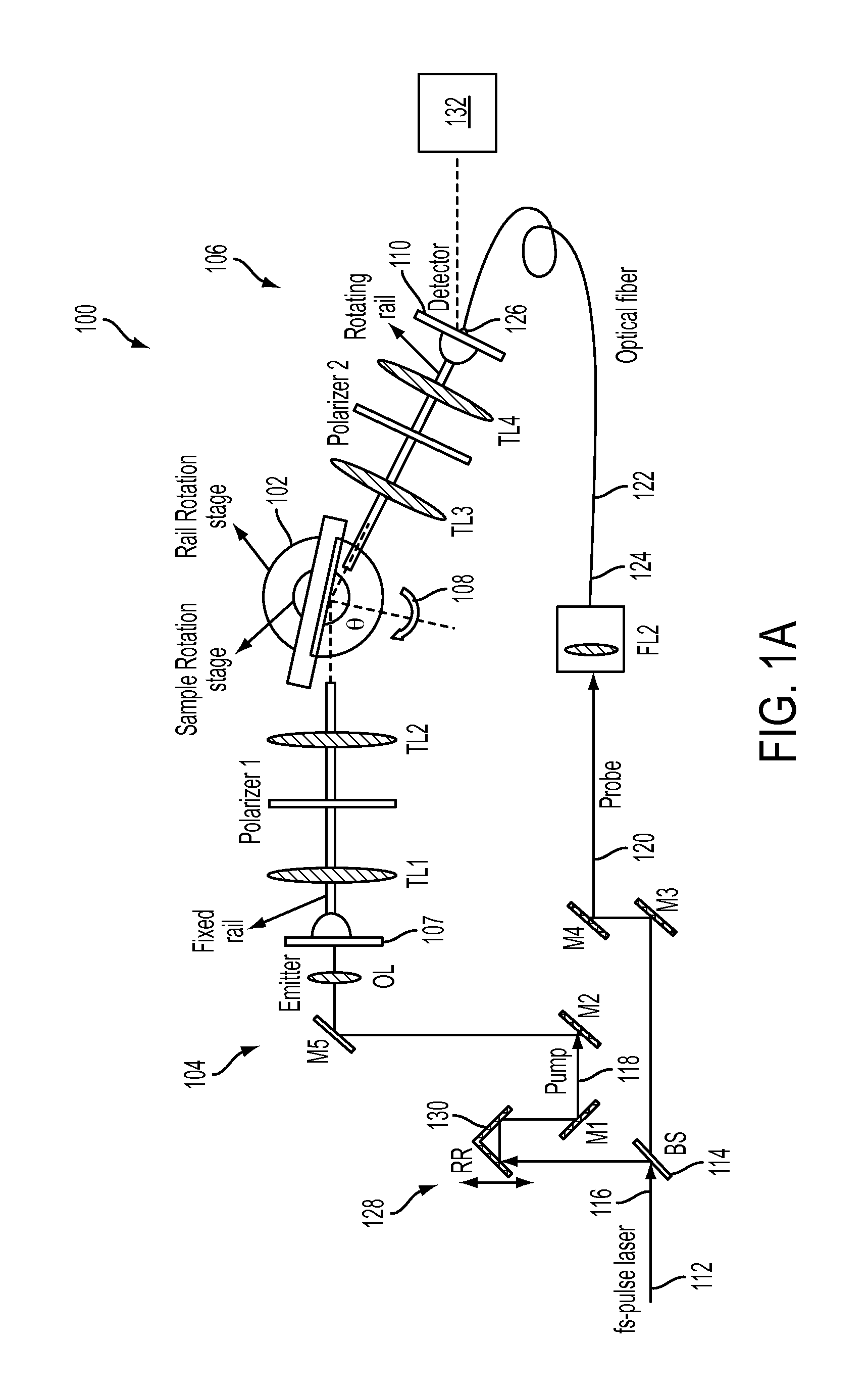
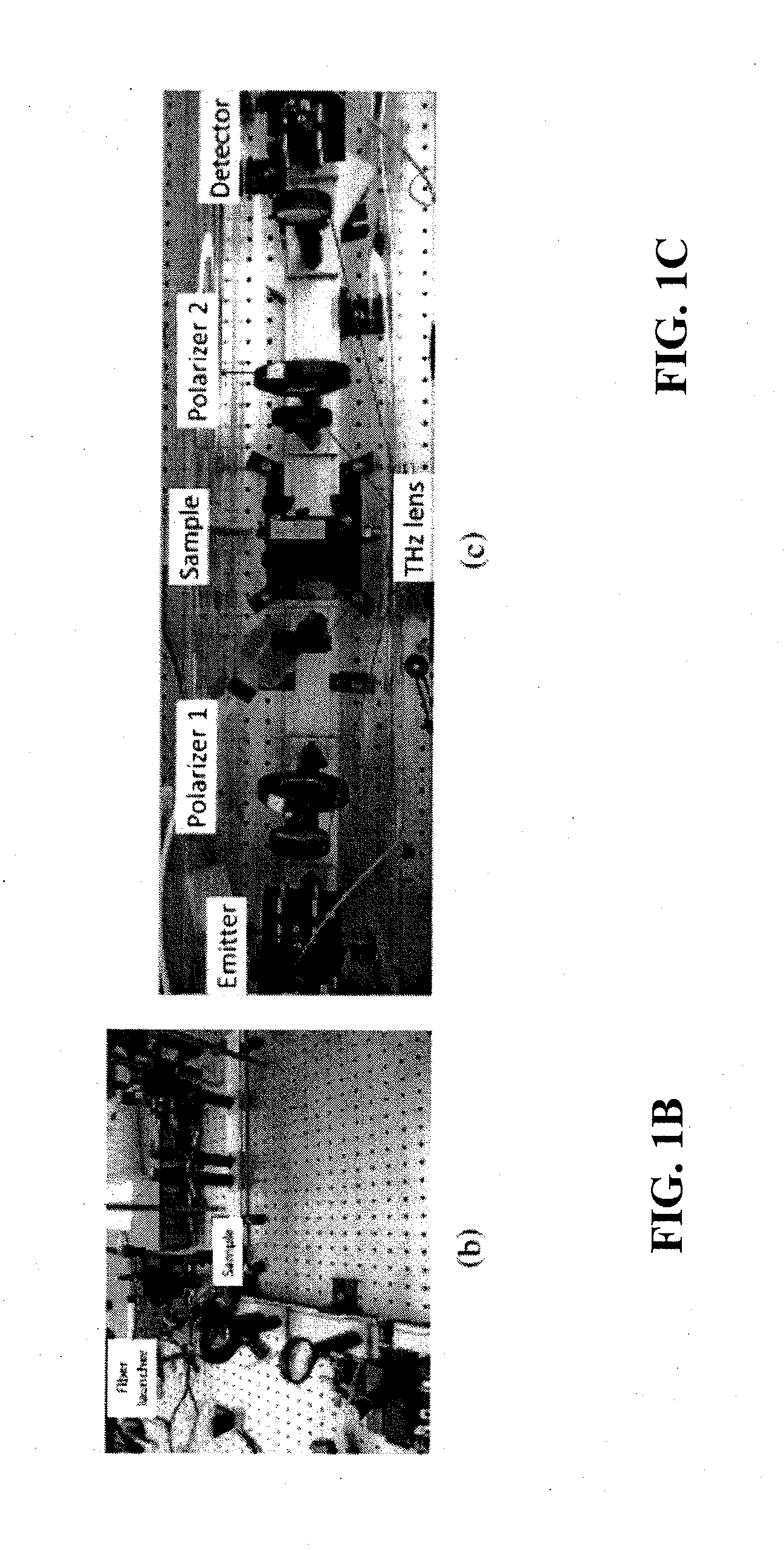
[0027]FIG. 1A illustrates an example of a terahertz time-domain spectroscopic ellipsometry system according to an embodiment of the current invention. In this system, the terahertz components are arranged on two straight arms using optical rails; one arm with THz emitter is fixed on the optical table, whereas the other arm with THz detector can rotate around a center point where the sample is placed. The sample sits on a second rotation stage. Such a configuration provides variable incidence angle (15°<θ<85°) in reflection mode, and can be easily configurable in transmission mode by aligning the arms along a straight line (FIG. 1C). In this schematic of the THz-TDSE setup with variable incidence angle in reflection mode that is also configurable in transmission mode optical components are labeled as follows, including a numerical value for each individual component (M, mirror; RR, retro-reflector; BS, optical beam splitter; OL, optical lens; TL, terahertz lens).

[0028]The setup uses ...


PUM


Abstract

A terahertz time-domain spectroscopic ellipsometry system includes a sample stage, a terahertz emitter configured to provide pulses of terahertz radiation with preselected polarization components to illuminate a sample on the sample stage along an incident direction, and a coherent terahertz detection system arranged to coherently detect pulses of terahertz radiation from the terahertz emitter along an emerging direction after at least one of reflecting from or passing through the sample. The sample stage is rotatable to vary a relative angle between the incident direction and the emerging direction, and the coherent terahertz detection system substantially maintains alignment for amplitude and polarization detection as the relative angle is varied.

Description

CROSS-REFERENCE OF RELATED APPLICATION[0001]This invention was made with Government support of Grant No. YFA N66001-10-1-4017, awarded by the DARPA. The U.S. Government has certain rights in this invention.BACKGROUND[0002]1. Field of Invention[0003]The field of the currently claimed embodiments of this invention relates to terahertz ellipsometry systems, and more particularly to terahertz time-domain spectroscopic ellipsometry systems.[0004]2. Discussion of Related Art[0005]Terahertz time-domain spectroscopy (THz-TDS) has tremendously grown with a wide range of applications [1]-[4]. It is now relatively routine to obtain complex (i.e. real and imaginary) spectral information, for instance the complex dielectric function, with absolute numerical values when performing measurements in a transmission geometry. However, transmission measurements are not possible on many materials and so far the technique has been difficult to apply to many metals, thick or highly doped semiconductors, c...

Claims


Application Information

Patent Timeline
Patent Type & Authority Applications(United States)
IPC IPC(8): G01J3/30G01J3/453
CPCG01J3/453G01J3/30G01J3/42G01N21/211G01N21/3586
Inventor NESHAT, MOHAMMADARMITAGE, N. PETER
Owner THE JOHN HOPKINS UNIV SCHOOL OF MEDICINE
Learn More