Multifunctional detabber apparatus and method

a detabber and multi-functional technology, applied in the field of detabber apparatus and methods, can solve the problems of high operating cost and high capital expenditure, and achieve the effect of optimizing the flow of bottles

Active Publication Date: 2014-09-18
GRAHAM PACKAGING CO LP
View PDF0 Cites 4 Cited by
  • Summary
  • Abstract
  • Description
  • Claims
  • Application Information

AI Technical Summary

Benefits of technology

[0005]To meet this and other needs, and in view of its purposes, the present invention provides for a space-saving, high-efficiency, automatic, multifunctional detabber apparatus that is able to handle and accurately perform a number of different functions in a single cycle. For example, the apparatus may achieve some or all of the following functions: (1) cutting, separating, or removing waste from the bottles (e.g., trimming waste from around a pre-molded hook projection); (2) forming hooks in the bottom of the bottles including creating the outer periphery of the hook and an opening in the hook; (3) folding or bending the hooks into a recess molded into the bottom of the bottles; (4) optimizing the flow of bottles; and (5) processing the bottles in a specific and reliable manner. The multifunctional detabber apparatus should be able to process up to about 40 bottles per minute.
[0009]The trimmer may be designed as one or more strikers or punches to produce the final shape of the hook projection and remove excess molding waste. The trimmer may include a first striker and a second striker, for example. The first striker may include a sharp edge or cutting surface contoured to create an outer periphery of the hook projection and the second striker may include a sharp edge or cutting surface designed to create an opening or hole in the hook projection. The trimmer may further comprise a counter-striker juxtaposed to the first striker and the second striker to aid in trimming and supporting waste produced in the trimming or punching operation. In particular, the cutting surfaces of the first and second strikers may coincide with a surface of the counter-striker. If the waste is properly cut off or removed in upstream operations or by the first and second strikers, activation of the counter-striker may not be required.
[0020]The multifunctional detabber apparatus is able to perform a number of different functions in a single-stage operation. The need for downstream operations, such as de-flashing, trimming, or hook closing, is made obsolete, which provides for performance efficiencies and cost savings in the overall operation. Accommodating multiple functions in one device minimizes losses and increases final efficiency versus multiple single, specialized devices for each function, which can potentially generate sum losses on each piece of equipment.

Problems solved by technology

In other words, multiple single, specialized devices are required for each function leading to high capital expenditures and high operating costs.

Method used


Image

  • Multifunctional detabber apparatus and method
  • Multifunctional detabber apparatus and method
  • Multifunctional detabber apparatus and method

Examples


Embodiment Construction

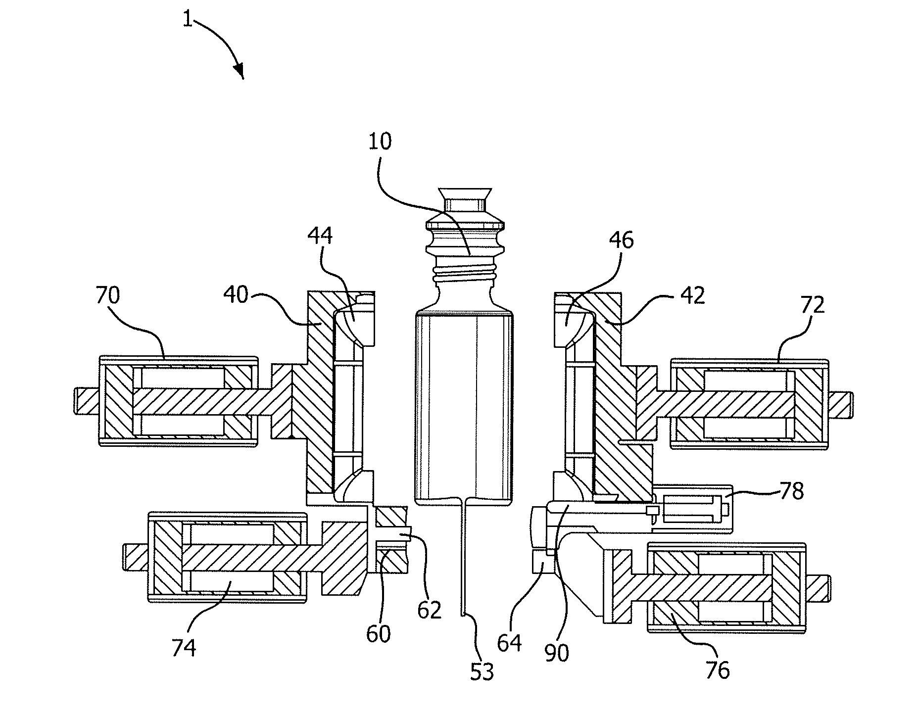
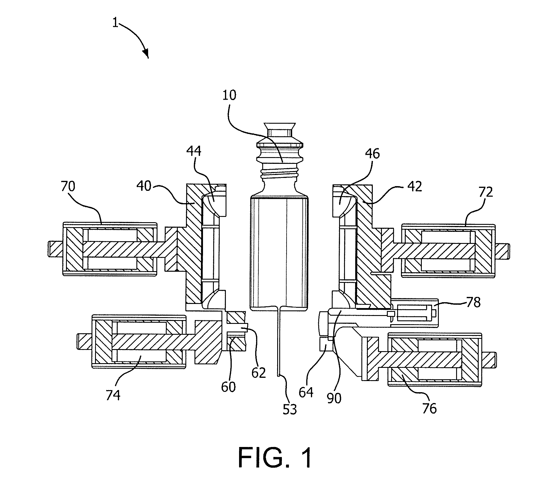
[0040]The present invention provides for a high-efficiency multifunctional detabber apparatus able to handle and accurately modify a plurality of bottles. The apparatus is able to perform a number of different functions in a single cycle of the apparatus in a precise and consistent manner. The multifunctional detabber apparatus is able to incorporate functionality including trimming operations and folding or bending operations. The present invention also provides a related method for performing these functions.

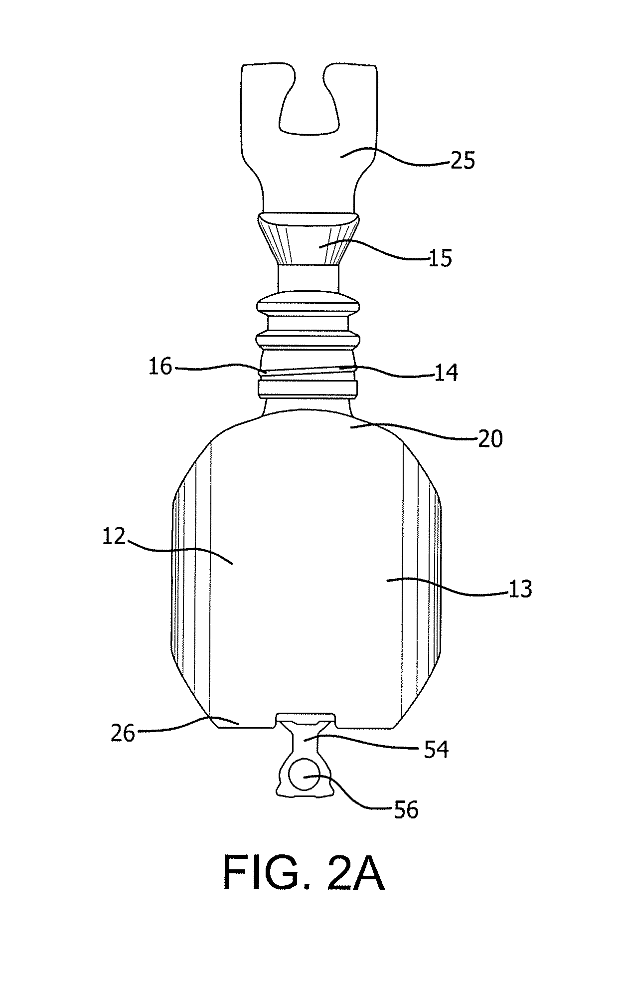
[0041]Referring now to the drawing, in which like reference numbers refer to like elements throughout the various figures that comprise the drawing, the present invention provides a multifunctional detabber apparatus 1 for producing a single bottle 10 in a single cycle of operation of the multifunctional detabber apparatus 1. FIG. 1 depicts a multifunctional detabber apparatus 1 according to one embodiment of the present invention, which may be used to produce bottles 10 havin...


PUM

PropertyMeasurementUnit
pressureaaaaaaaaaa
pressureaaaaaaaaaa
pressureaaaaaaaaaa

Abstract

A multifunctional detabber apparatus and method for producing bottles having a bottom surface with a hook projection integrally molded with and extending from the bottom surface in a deployed position. The bottom surface also includes at least one locking channel in order to receive and releasably secure the hook projection in a non-deployed position. The multifunctional detabber apparatus includes at least a grabber, a trimmer, and a hook closer. The grabber includes first and second jaws which surround the bottle and prevent movement. The trimmer includes first and second strikers for creating an outer periphery of the hook projection and an opening in the hook projection. The hook closer includes a mandrel that extends to bend and secure the hook projection in the locking channel in the bottom surface of the bottle.

Description

TECHNICAL FIELD[0001]The present invention relates generally to detabber apparatus and methods of trimming waste, forming a hook, and closing the hook in the bottom of bottles, containers, and like objects.BACKGROUND OF THE INVENTION[0002]When bottles, vessels, or like articles are manufactured, the bottles may need to undergo a number or series of process steps, such as molding, trimming, finishing, packaging, and the like to obtain the desired bottle design. The process steps may require a number of highly specialized types of equipment to perform individualized tasks. In other words, multiple single, specialized devices are required for each function leading to high capital expenditures and high operating costs.[0003]With the introduction of bottles designed with a hook or hanger provided on the base of the bottle such that the bottle is able to be suspended or hung by its base, even more manufacturing steps may be required. Depending on the placement, type, and configuration of ...

Claims


Application Information

Patent Timeline
Patent Type & Authority Applications(United States)
IPC IPC(8): B29C53/02B29C49/42
CPCB29C49/4273B29C53/02B29L2031/716B29C49/04B29C49/541B29C49/72B29C2793/009B29L2031/7158B29C49/50B29C2049/503B29C2793/0009B29C2949/0791B29C49/4283B29C37/02B29C67/0048B29C69/001B29L2031/738
Inventor KOZAK, LESZEKWOINSKI, GRZEGORZSTRUPINSKI, SLAWOMIR
Owner GRAHAM PACKAGING CO LP
Why Eureka
Try Eureka