Pressure-compensated transducer assembly

a transducer and assembly technology, applied in the direction of mechanical vibration separation, piezoelectric/electrostrictive/magnetostrictive devices, piezoelectric/electrostrictive/magnetostriction machines, etc., can solve the problems of inability to fully satisfy, and inability to meet the demands of high-pressure and high-temperature transducers

Inactive Publication Date: 2014-09-18
PIEZO TECH
View PDF3 Cites 3 Cited by
  • Summary
  • Abstract
  • Description
  • Claims
  • Application Information

AI Technical Summary

Benefits of technology

[0010]A relatively non-compressible fluid is provided in the first interior space, and extends into the connection end channe

Problems solved by technology

It is known to use piezoelectric transducers in downhole drilling environments that present high-pressure and high-temperature challenges to the transducer.
When the pressure presented by the environment exceeds the pressure insid

Method used


Image

  • Pressure-compensated transducer assembly
  • Pressure-compensated transducer assembly
  • Pressure-compensated transducer assembly

Examples


Embodiment Construction

[0015]For the purposes of promoting an understanding of the principles of the invention, reference will now be made to certain preferred embodiments and specific language will be used to describe the same. It will nevertheless be understood that no limitation of the scope of the invention is thereby intended, such alterations and further modifications in the illustrated device, and such further applications of the principles of the invention as illustrated therein being contemplated as would normally occur to one skilled in the art to which the invention relates.

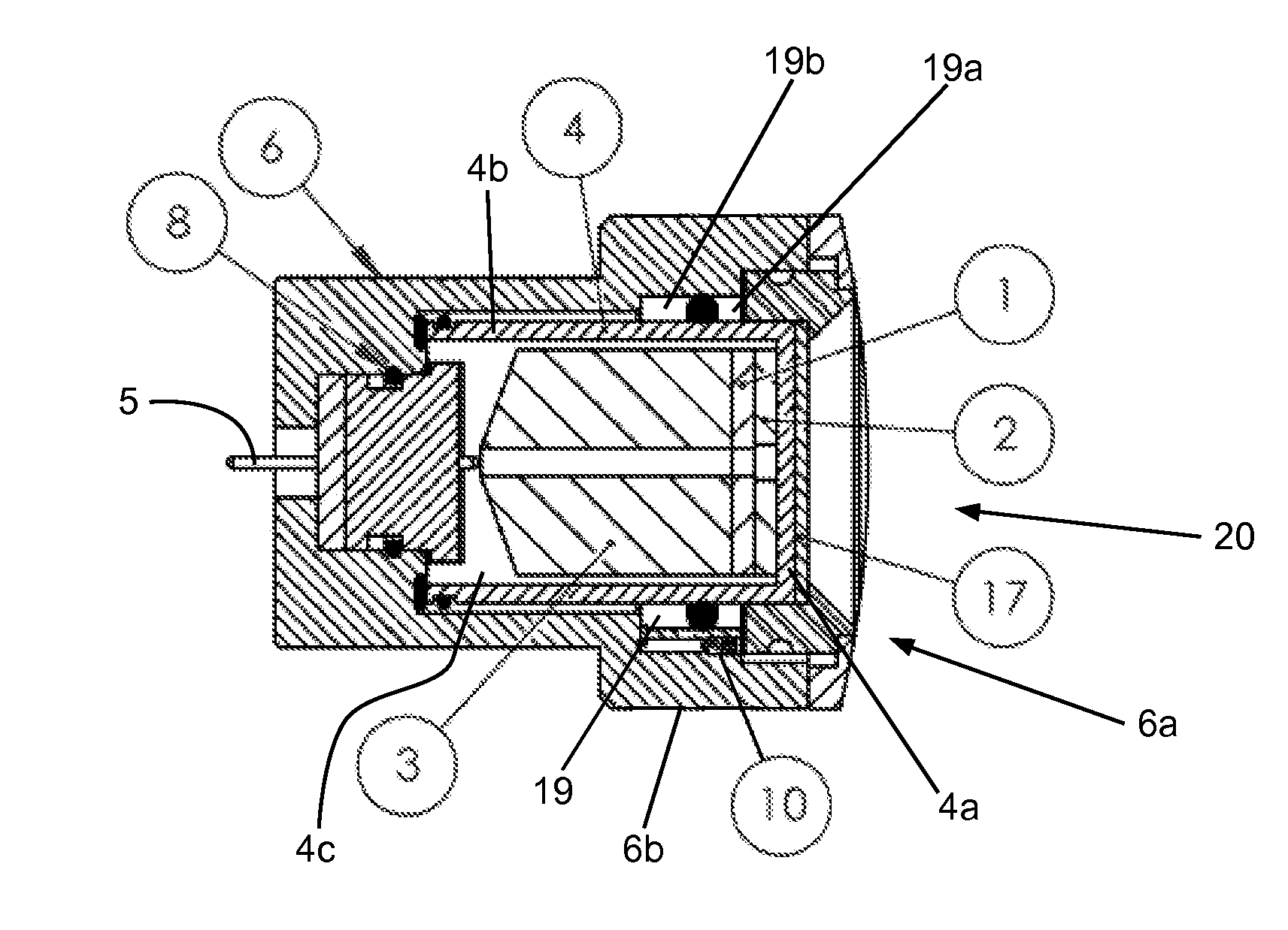
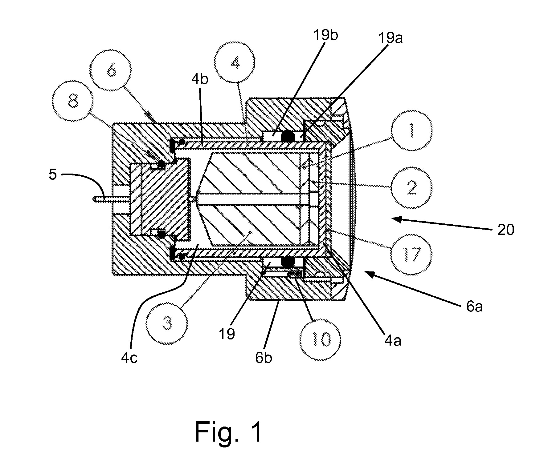
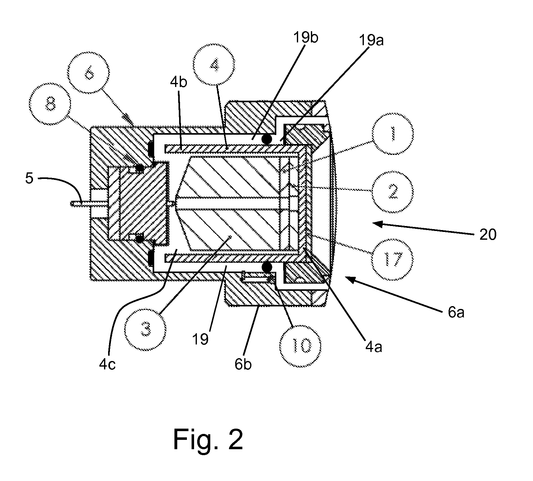
[0016]As indicated above, one embodiment of the present invention provides a pressure-compensated transducer assembly that may be used as a sensor in an environment such as a downhole oilfield well. Such transducers may use piezoelectric materials to send and receive acoustic waves. The assembly is typically connected to electronic controls at one end and propagates acoustic waves from the other end. Accordingly, for the pur...


PUM


Abstract

A pressure-compensated transducer assembly has an inner housing with a closed transducer end and an outer housing with an open transducer end. A piezoelectric assembly is in the closed transducer end of the inner housing. A liquid-filled inter-housing space is between the outer housing and the inner housing, and has a transducer end open to the environment and a connection end open to the piezo assembly space. A blocking member separates the transducer end of the inter-housing space from the connection end, and prevents fluids from flowing between the two ends. The blocking member is movable within the inter-housing space in response to pressure differences the environment and the interior space.

Description

REFERENCE TO RELATED APPLICATION[0001]This application claims the benefit of U.S. Provisional Patent Application No. 61 / 786,808, filed Mar. 15, 2013, the entire contents of which is hereby incorporated by reference into the present application.[0002]It is known to use piezoelectric transducers in downhole drilling environments that present high-pressure and high-temperature challenges to the transducer. Such environments may have pressures of 25K psi or more, and may have temperatures in excess of 600° F.[0003]When the pressure presented by the environment exceeds the pressure inside the transducer, the performance of the transducer may be compromised. Various mechanisms for adjusting the internal pressure in response to outside pressure changes have been devised, but none have proven completely satisfactory.[0004]A need therefore exists for a pressure compensated assembly for housing a piezoelectric transducer or other functional element. The present invention addresses that need.S...

Claims


Application Information

Patent Timeline
IPC IPC(8): B06B1/06H01L41/053
CPCH01L41/053B06B1/0644
Inventor DALLAS, JAMES MICHAELLAUTZENHISER, FRANS
Owner PIEZO TECH
Why Eureka
Try Eureka