Lossless preload for LED driver with extended dimming

a technology of led lamps and preloads, which is applied in the direction of electric variable regulation, process and machine control, instruments, etc., can solve the problems of limited dimming range, flickering, blinking, and/or color shifting in led lamps, and may be noticed

Inactive Publication Date: 2014-09-18
POWER INTEGRATIONS INC
View PDF3 Cites 60 Cited by
  • Summary
  • Abstract
  • Description
  • Claims
  • Application Information

AI Technical Summary

Problems solved by technology

However, flicker may be noticed when Triac circuits are used for dimming LED lamps.
Unless the regulated power supplies that drive the LED lamps are designed to recognize and respond to the voltage signals from Triac dimming circuits in a desirable way, the Triac dimming circuits are likely to produce non-ideal results, such as limited dimming range, flickering, blinking, and / or color shifting in the LED lamps.
The difficulty in using Triac dimming circuits with LED lamps is in part due to a characteristic of the Triac itself.
However, the comparably low currents drawn by LEDs from efficient power supplies may not meet the minimum holding currents required to keep the Triac switches conducting for reliable operation.
As a result, the Triac may trigger inconsistently.
In addition, due to the inrush current charging the input capacitance and because of the relatively large impedance that the LEDs present to the input line, a significant ringing may occur whenever the Triac turns on.
This ringing may cause even more undesirable behavior as the Triac current may fall to zero and turn off the string of LEDs, resulting in a flickering effect.
While useful to draw additional current, a bleeder circuit that is external to the integrated circuit requires the use of extra components with associated penalties in cost and efficiency.

Method used


Image

  • Lossless preload for LED driver with extended dimming
  • Lossless preload for LED driver with extended dimming
  • Lossless preload for LED driver with extended dimming

Examples


Embodiment Construction

[0018]In the following description, numerous specific details are set forth in order to provide a thorough understanding. It will be apparent, however, to one having ordinary skill in the art that the specific details need not be employed.

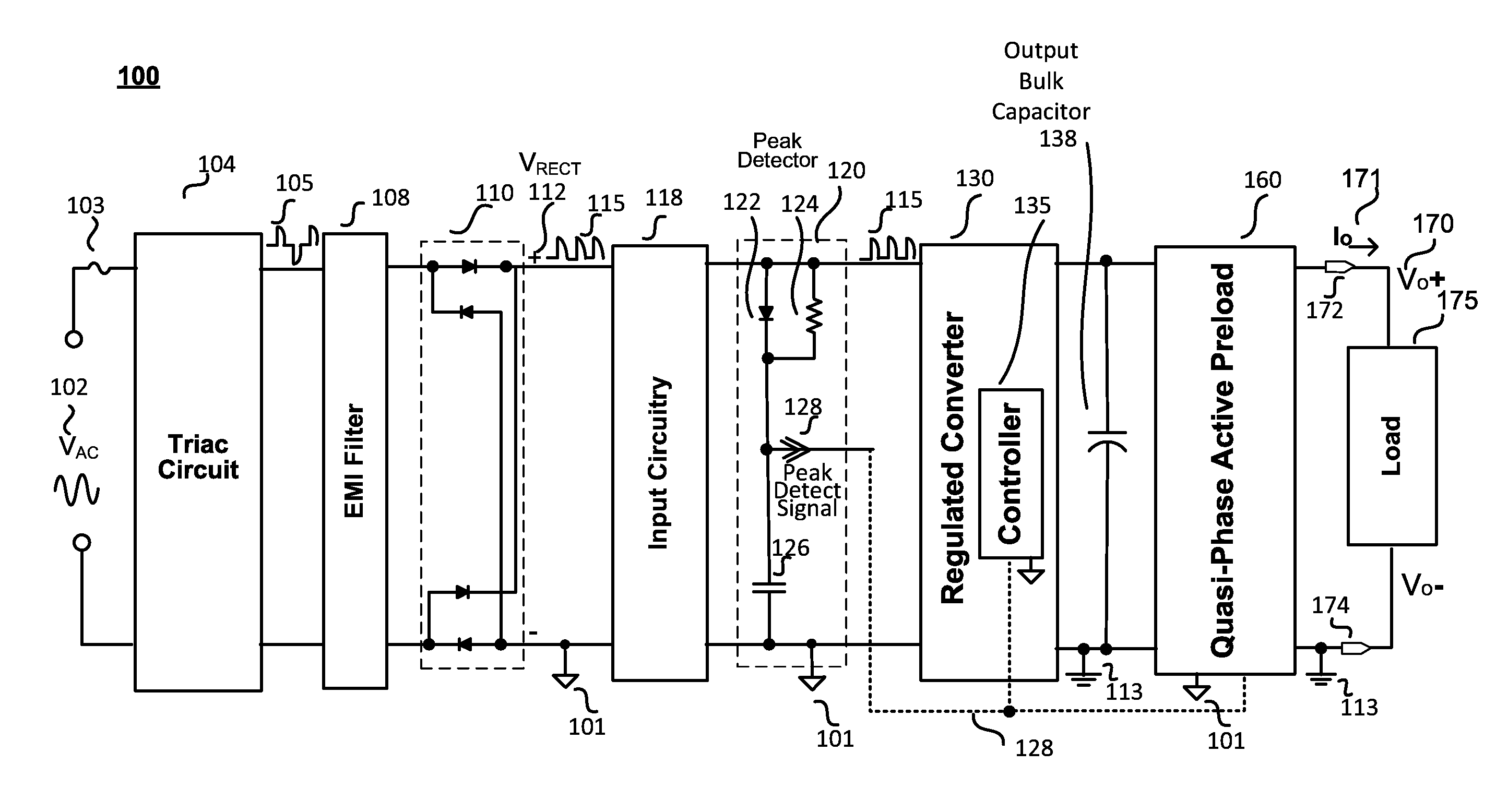
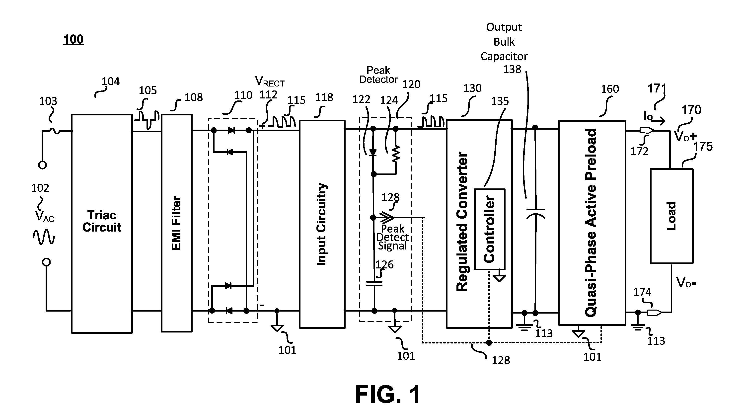
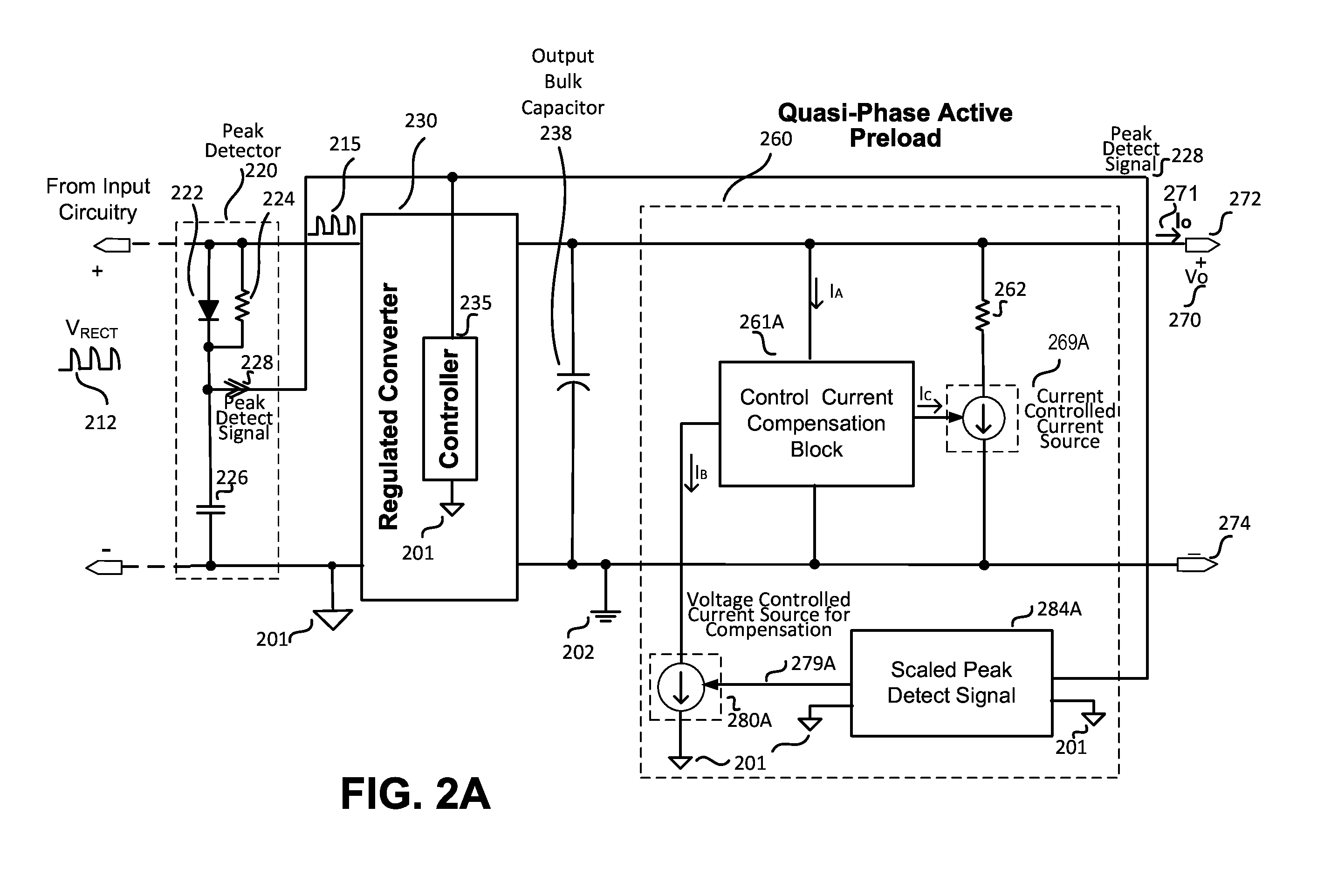
[0019]Various embodiments directed to quasi-phase active preload circuitry for an LED driver implementing phase-angle dimming are disclosed. The quasi-phase active preload circuitry disclosed in this application may be used with any type of phase-angle control dimmer that either controls the leading edge or trailing edge of the line voltage cycle. In a more specific example explained in greater detail below, it may be used with a Triac leading edge phase-angle control dimmer by indirectly (e.g., through leading edge peak detection) being responsive to the Triac conduction angle, which is referred to as quasi-phase detection. The circuitry provides a reliable and improved performance with extended dimming ratio and high efficiency for the LED driver...


PUM


Abstract

A quasi-phase active preload circuit to be coupled at the output of a non-isolated LED driver converter having a pre-stage phase-angle control dimmer circuit, such as a commonly used leading-edge control Triac dimmer, is disclosed. The quasi-phase active preload circuit may include a preload resistor coupled to a current-controlled current source configured to draw a sinking current through the preload resistor based on a peak detect signal. The peak detect signal may be, in one example, representative of a leading-edge peak voltage of an output of the Triac dimmer circuit, which may be representative of a conduction angle of the Triac dimmer circuit. During normal operating conditions, no sinking current is drawn through the preload resistor. During low dimming conditions, a sinking current that is responsive to the peak detect signal is drawn through the preload resistor. During deep dimming or when used with a leaky Triac dimmer, a maximum sinking current may be drawn through the preload resistor by the current-controlled current source.

Description

BACKGROUND[0001]1. Field[0002]The present disclosure relates generally to circuits for driving light-emitting diodes (LEDs) and, more specifically, to LED driver circuits having phase-angle dimming circuitry.[0003]2. Related Art[0004]LED lighting has become popular in the industry due to the many advantages that this technology provides. For example, LED lamps typically have a longer lifespan, pose fewer hazards, and provide increased visual appeal when compared to other lighting technologies, such as compact fluorescent lamp (CFL) or incandescent lighting technologies. The advantages provided by LED lighting have resulted in LEDs being incorporated into a variety of lighting technologies, televisions, monitors, and other applications.[0005]It is often desirable to implement LED lamps with a dimming functionality to provide variable light output. One known technology that has been used for analog LED dimming is the phase angle dimming either by leading edge or trailing edge control....

Claims


Application Information

Patent Timeline
Patent Type & Authority Applications(United States)
IPC IPC(8): H05B33/08H05B44/00
CPCH05B33/0815H05B45/10Y02B20/30H05B45/3725H05B45/375H05B45/31
Inventor DEL CARMEN, JR., JOSE R.ESPINO, MARVIN CRUZ
Owner POWER INTEGRATIONS INC
Why Eureka
Try Eureka