System and method for filling gaps in radar coverage

Active Publication Date: 2014-09-18
LAPOINT BLASE IND +1
View PDF26 Cites 7 Cited by
  • Summary
  • Abstract
  • Description
  • Claims
  • Application Information

AI Technical Summary

Benefits of technology

[0008]In accordance with one aspect, there is provided a method of positioning a plurality of radar units in a defined area amongst one or more legacy radar units that provide legacy radar coverage in the defined area. The method includes the steps of identifying a location of each legacy radar unit, setting a threshold altitude, and determining a legacy occultation of each legacy radar unit from a landscape level up to the threshold altitude. The method also includes mapping the legacy occultation of the legacy radar units to provide a three dimensional occultation map in the defined area and locating gaps below the threshold altitude in the legacy radar coverage as a function of the occultation map. The method also includes identifying a plurality of sites as a function of the gaps where the sites are accessible to receive a radar unit. The method also includes determining an anticipated radar coverage of a radar unit positioned at each of the sites and determining a reduction in the gaps as a function of the anticipated radar coverage. The method also includes selecting sites as a function of the reduced gaps.
[0009]The method may include the step of positioning an X band, C band or S band radar unit at the selected sites. The threshold altitude can be less than 500, 1,000, 5,000, 10,000, 12,000 or 15,000 feet. A percentage of the occultation map below the threshold altitude corresponding to the gaps can be calculated. The calculated percentage can be reduced as a function of the anticipated radar coverage and the sites can be selected as a function of the reduced percentage corresponding to the gaps. A population associated with the gaps can also be calculated and the calculated population can be reduced as a function of a reduction in the gaps corresponding to the anticipated radar coverage. The sites can be selected as a function of the reduced calculated population. A cost can be associated with each of the sites and the sites can be selected as a function of the reduced gaps and of the cost associated with the sites.
[0010]In accordance with another aspect, there is provided a computer system containing computer executable instruct

Problems solved by technology

However, the resulting coverage for a planned network is typically derived by trial and error in the placement of the individual component syste

Method used


Image

  • System and method for filling gaps in radar coverage
  • System and method for filling gaps in radar coverage
  • System and method for filling gaps in radar coverage

Examples


Embodiment Construction

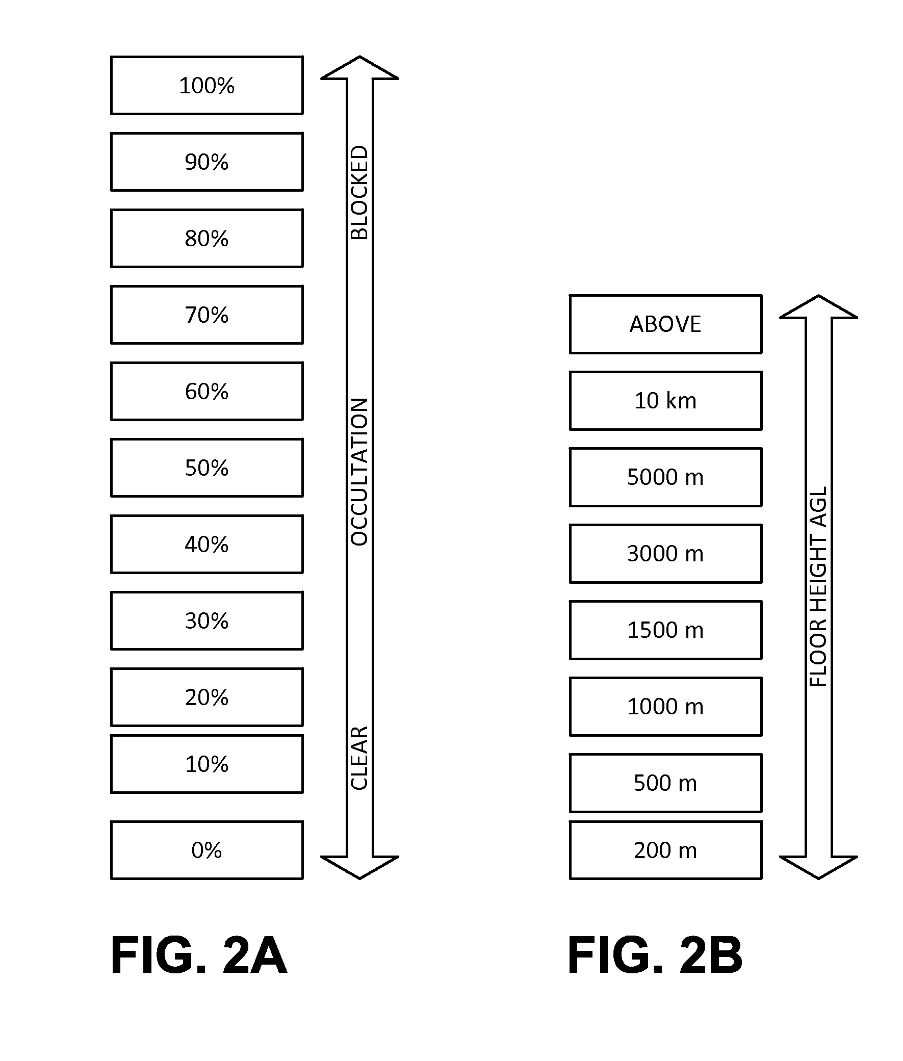
[0027]The performance of legacy radar systems can be improved and enhanced ad hoc by placing smaller radar units at locations which fill in the gaps of the existing system. The innovation described herein provides a means to define the number and characteristics of gap-filling systems which can be added to an existing sensor network and which will result in a higher level of overall system performance. This provides a higher level of performance in hazard detection and warning by the entire system or network using fewer radar sites. This also provides the ability to accurately forecast the performance of gap-filling systems before they are installed which greatly enhances the gap-filling process.

[0028]When filling the gaps in a legacy system, the performance characteristics of the existing sensor system are determined so that the Shipley Floor for those legacy sensors in their respective geographic locations can be generated. The performance characteristics of the available sensors ...


PUM


Abstract

A method of positioning a plurality of radar units in a defined area amongst one or more legacy radar units that provide legacy radar coverage in the defined area is disclosed. The steps of identifying a location of each legacy radar unit, setting a threshold altitude, and determining a legacy occultation of each legacy radar unit from a landscape level up to the threshold altitude are also disclosed. Mapping the legacy occultation of the legacy radar units to provide a three dimensional occultation map in the defined area and locating gaps below the threshold altitude in the legacy radar coverage as a function of the occultation map are also disclosed. Identifying a plurality of sites as a function of the gaps where the sites are accessible to receive a radar unit is also disclosed. Determining an anticipated radar coverage of a radar unit positioned at each of the sites and determining a reduction in the gaps as a function of the anticipated radar coverage are also disclosed. Selecting sites as a function of the reduced gaps is also disclosed. X band, C band or S band radar units can be positioned at the selected sites. The threshold altitude can be 10,000 or 15,000 feet. Affected populations and costs can also be considered in radar placement.

Description

CROSS-REFERENCE TO RELATED APPLICATIONS[0001]This application is a nonprovisional patent application which claims the benefit of U.S. Provisional Patent Application Ser. No. 61 / 799,478 filed Mar. 15, 2013, the entire disclosure of which is incorporated by reference.FIELD OF THE INVENTION[0002]The present invention generally relates to a system and method for identifying gaps in a legacy radar system and then filling those gaps with selected equipment.BACKGROUND OF THE INVENTION[0003]Weather Radars are deployed in fixed-based and mobile networks to detect hazardous weather and provide advance warnings of approaching severe weather to people and their representatives, to industries for improved safety and performance, and to military and government entities for improved operations and risk abatement. The effectiveness of a single radar and a network or collection of radars is dependent on a number of factors that impact the operational performance of each radar system. Such factors in...

Claims


Application Information

Patent Timeline
IPC IPC(8): G01S13/02
CPCG01S13/02G01S7/02G01S13/951Y02A90/10G01S13/872
Inventor LAPOINT, DONALD A.BLASE, GUY E.SHIPLEY, SCOTT
Owner LAPOINT BLASE IND
Why Eureka
Try Eureka