Display device

Active Publication Date: 2014-09-18
JAPAN DISPLAY INC
View PDF3 Cites 5 Cited by
  • Summary
  • Abstract
  • Description
  • Claims
  • Application Information

AI Technical Summary

Benefits of technology

[0008]In recent years, there has been a significant increase in the number of display pixels in the portable information terminal in order to improve the display quality of the liquid crystal display device in a housing of a limited size. At the same time, it is desirable to reduce the peripheral portion of the display area, which does not contribute to image

Problems solved by technology

However, the back surface of the protective plate has a difference in level due to the printing of the light shielding film.
This leads to a problem that bubbles a

Method used


Image

  • Display device
  • Display device
  • Display device

Examples


Example

First Embodiment

Overall Configuration

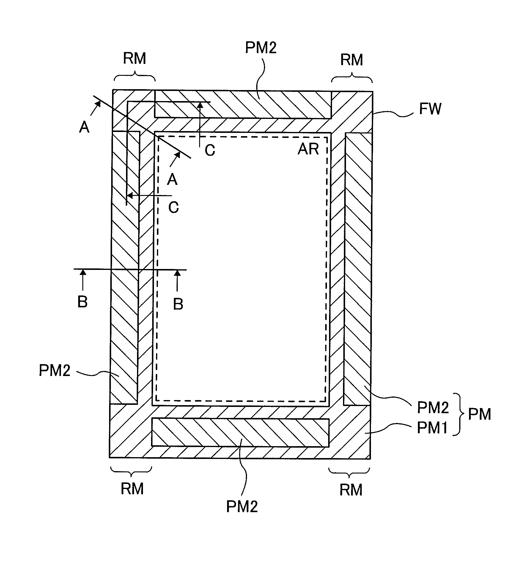
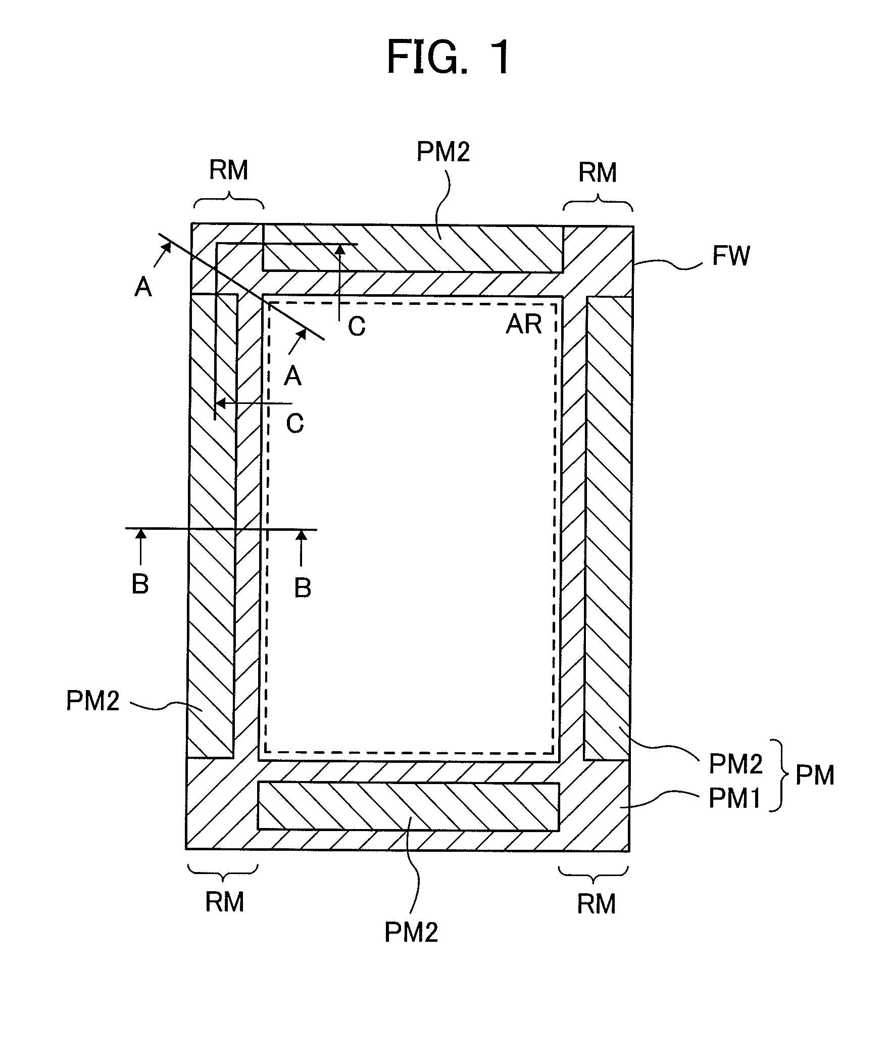
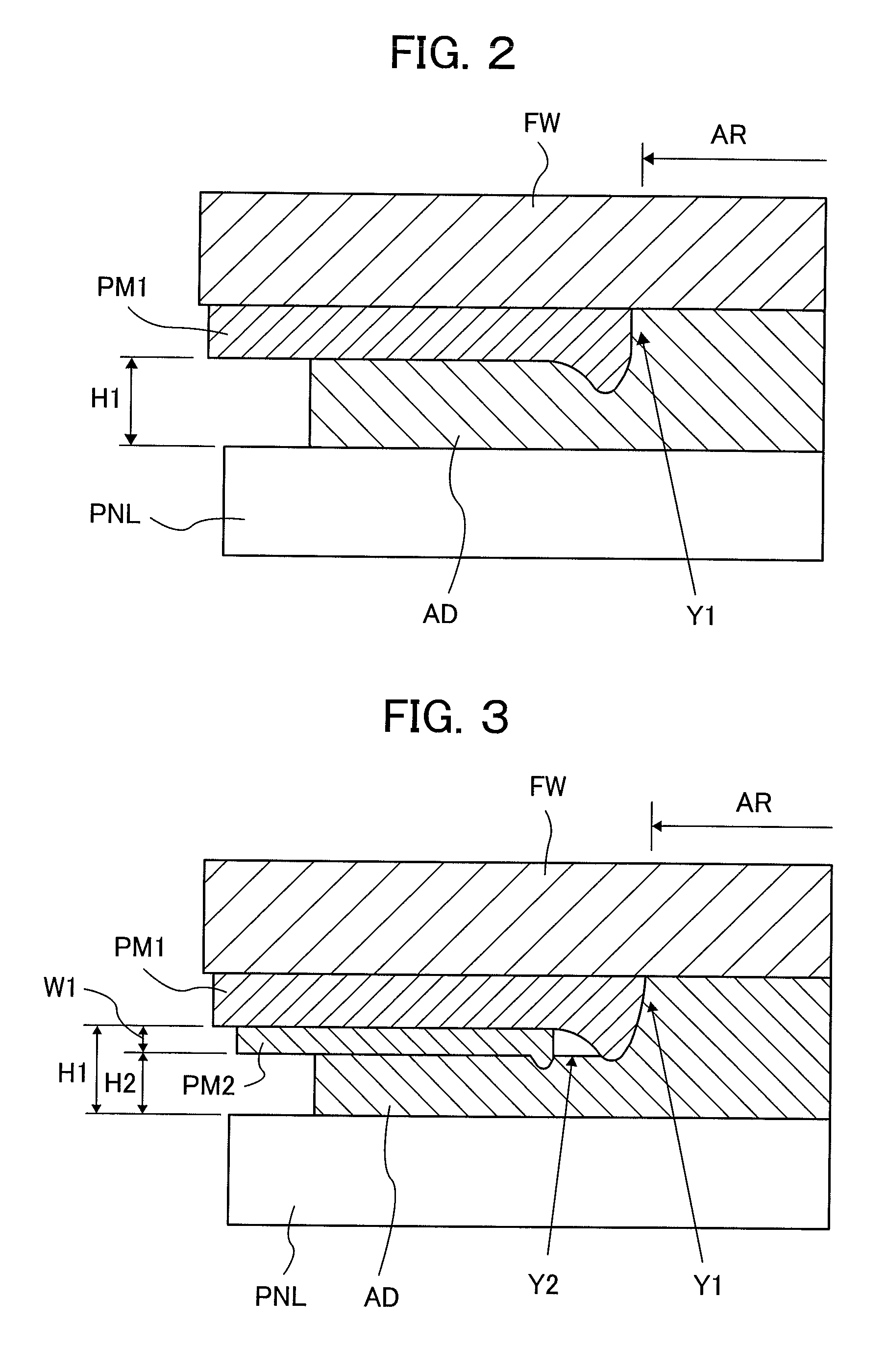
[0025]FIG. 1 is a plan view showing a schematic configuration of a liquid crystal display device which is a display device according to a first embodiment of the present invention. Hereinafter, the configuration of a protective plate FW of the display device according to the first embodiment will be described based on FIG. 1. In the following, it is assumed that the protective plate FW is bonded to the front surface of a display panel PNL formed by a liquid crystal display panel and a backlight device. However, other display panels such as a known organic EL display panel may be used. The present invention can also be applied to the configuration in which the protective plate FW is bonded to the front surface of a display panel in which a coordinate input device such as a known touch panel is provided in the front surface of the liquid crystal display panel or in the front surface of the organic EL display panel. Further, the present invention ca...

Example

Second Embodiment

[0046]FIG. 5 is a front view showing a schematic configuration of a liquid crystal display device which is a display device according to a second embodiment of the present invention. FIG. 4 corresponds to FIG. 1 in the first embodiment. Note that the display device according to the second embodiment has the same configuration as the first embodiment, except for the formation position of the second light shielding film PM2, namely, the area RM where the second light shielding film PM2 is not formed. Thus, the second light shielding film PM2 will be described in detail below.

[0047]Also in the display device according to the second embodiment, similarly to the first embodiment, the drive circuit of the liquid crystal display panel is mounted on the lower edge of the display panel not shown (on the lower side of the display panel in the figure). Then, the flexible wiring substrate is connected to the drive circuit to input control signals. At this time, the width of the...


PUM


Abstract

A display device includes: a display panel, a protective plate provided in a front surface of the display panel to protect the display panel; and a light shielding film. The protective plate is fixed to the display panel by a transparent adhesive applied to an area between the display panel and the protective plate. The light shielding film is formed so as to surround a display area of the display panel, including a first light shielding film formed in a frame shape, and a second light shielding film deposited on the first light shielding film. The second light shielding film has a cut-out area where the second light shielding is not formed in at least one or more corner portions of the protective plate. A concave portion is formed in the corner portion of the light shielding film from an inner peripheral edge to an outer peripheral edge.

Description

CLAIM OF PRIORITY[0001]The present application claims priority from Japanese Patent Application JP 2013-54519 filed on Mar. 18, 2013, the content of which is hereby incorporated by reference into this application.BACKGROUND[0002]The present invention relates to a display device, and more particularly to a display device including a protective plate provided in the front surface of a display panel to protect the display panel.[0003]In portable information terminals such as a mobile phone with a liquid crystal display device as a display device, the liquid crystal display device is formed by a liquid crystal display panel and a backlight device for emitting illumination light to the liquid crystal display panel. In general, the display device has a module structure in which a protective plate (front window) is fixed to the front surface (observer side surface) of the liquid crystal display device to protect the liquid crystal display panel formed of a glass substrate.[0004]In the disp...

Claims


Application Information

Patent Timeline
IPC IPC(8): G02F1/1335
CPCG02F1/133512G02F1/133308G02F2001/13332G02F2001/133331G02F2202/28G02F1/13332G02F1/133331
Inventor KONDO, YASUAKI
Owner JAPAN DISPLAY INC
Why Eureka
Try Eureka